Anti-backlash device in a gear

a technology of anti-backlash and gear, which is applied in the direction of gearing elements, belts/chains/gearrings, hoisting equipments, etc., can solve the problems of device not allowing adjusting the prestressing in accordance, weakening the wheel, and device not allowing the use of a wheel of small diameter, etc., to achieve constant prestressing force

Active Publication Date: 2008-12-23
BOBST SA
View PDF14 Cites 6 Cited by
  • Summary
  • Abstract
  • Description
  • Claims
  • Application Information

AI Technical Summary

Benefits of technology

[0010]Another advantage of the present invention results from the length of the bars not being limited by the dimensions of the toothed members, as in prior art devices. Now, the longer are the bars, the less the value of the prestressing exerted by the bars changes when variation of the distance between the axles occurs. Due to this, the present invention is not restricted to a fixed axle distance. Since the backlash varies according to the axle distance and the more the deflection bars are extended, then the less the prestressing varies according to the axle distance variation, and an approximately constant prestressing force for different axle distances is possible. This is not the case with devices in which the length of the prestressing springs is limited by the dimension of the wheels. Due to this fact, the torque transmittable by the gear using the anti-backlash device of the present invention practically does not vary according to the backlash to be eliminated.
[0011]The enclosed drawings illustrate, schematically, an exemplary embodiment of the anti-backlash device of the present invention.

Problems solved by technology

Such a device requires three wheels, and the presence of elastic blocks crossing two of the wheels does not allow using wheels or gears of small diameter, capable of transmitting a high torque, because the presence of holes weakens the board of the wheel, so that an adequate space has to be left between the edge of the holes and the bottom of the toothing.
These openings weaken the wheel and do not allow use of a wheel of small diameter.
In addition, this device does not allow adjusting the prestressing in accordance with the torque to be transmitted but allows only one determined stress.

Method used


Image

  • Anti-backlash device in a gear
  • Anti-backlash device in a gear
  • Anti-backlash device in a gear

Examples


Embodiment Construction

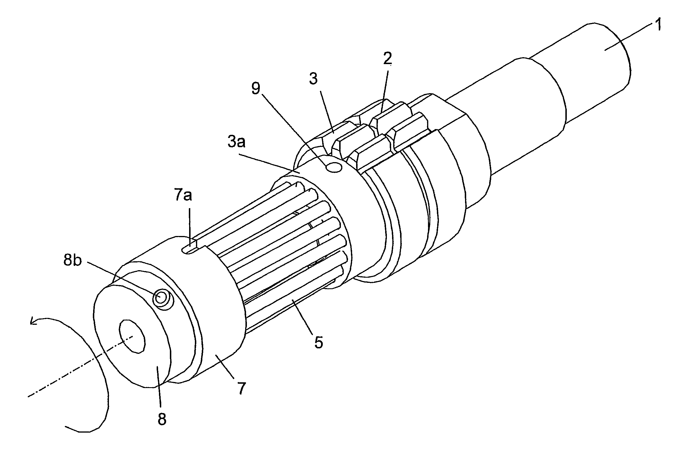
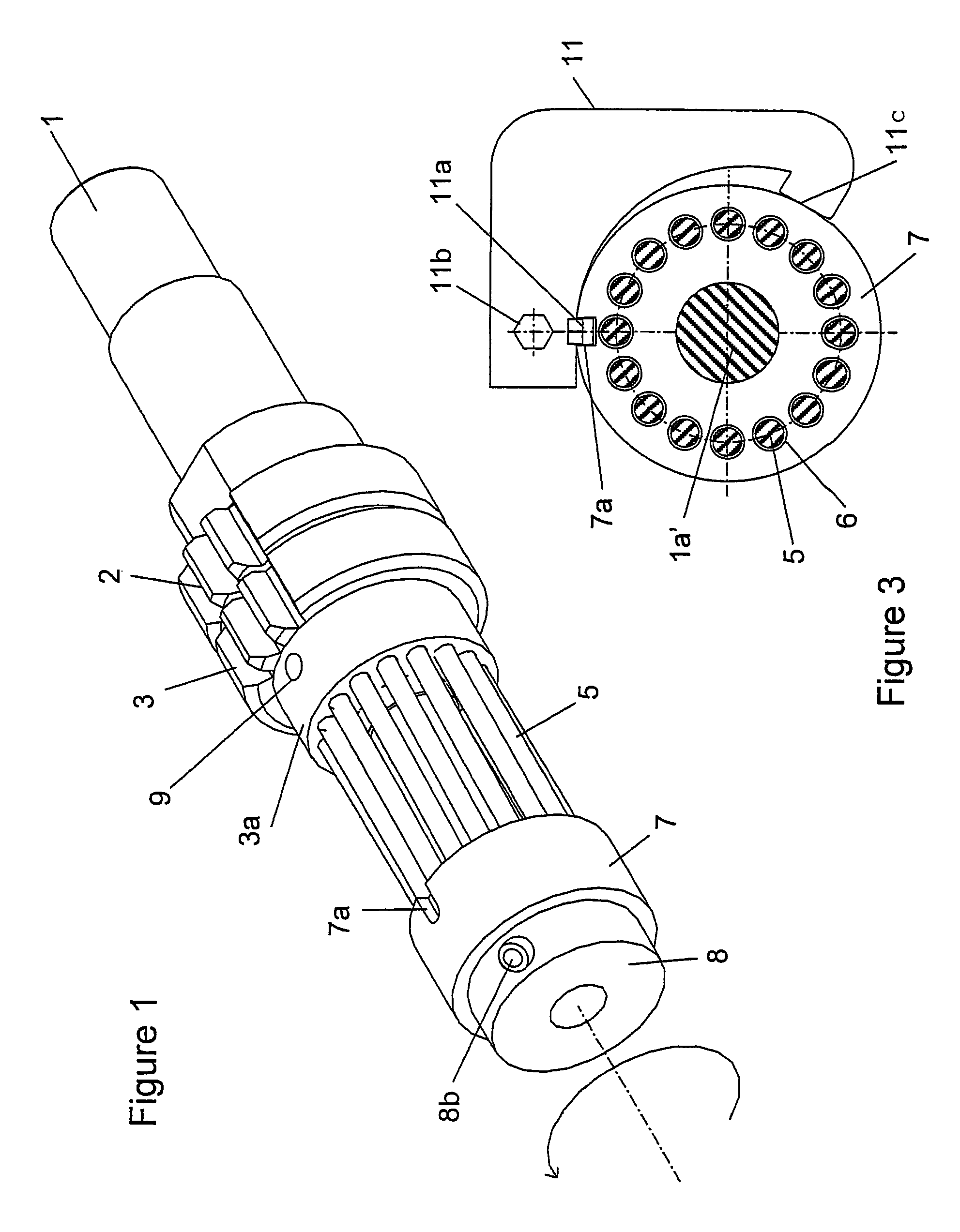
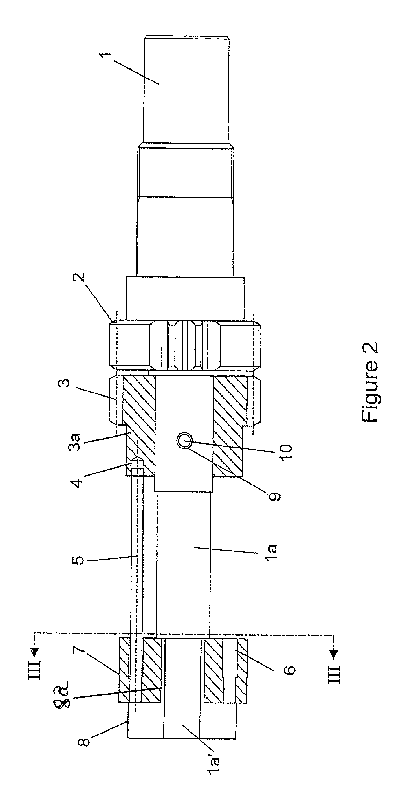
[0015]An anti-backlash device according to the present invention comprises a shaft 1 fixedly attached to a first toothed member 2. Although only two of the teeth are shown in the Figures, this is a conventional gear toothed around its entire circumference. The shaft 1 is elongated by a part 1a, with which the anti-backlash members of the gear are associated.

[0016]The first one of the members is a second toothed member 3, having toothing illustrated as identical to the toothing of the first toothed member 2. In this example, the second toothed member 3 comprises a non-toothed part 3a, on the side opposite to the first toothed member 2. A series of seats 4, of which only one is shown in FIG. 2, open on the planar face turned outward toward the exterior of the second toothed member 3. In this example, the seats 4 extend along a radially lower depth than the axial length of the non-toothed part 3a of the second toothed member 3. Due to this location, the seats 4 do not weaken the toothe...


PUM


Abstract

A driving element is divided into two coaxial toothed members elastically attached to one another. A first of the toothed members is fixed to a shaft. The second of the toothed members is freely mounted on this shaft. The second toothed member has a planar face, opposite and facing away from the first toothed member. That face has seats arranged around the shaft to receive first respective ends of deflection rods. The rods extend, with the shaft, outside of the toothed member. A flange has an axial passage for receiving an end of the shaft. The flange has seats for receiving second respective ends of the deflection rods. A device for clamping the flange on the end of the shaft and in an angular position around the shaft fitted to apply a deflection stress to the rods.

Description

BACKGROUND OF THE INVENTION[0001]The present invention refers to a anti-backlash device in a gear in which a toothed driving element is divided into two coaxial toothed members attached to one another by elastic means adapted to create a torque between these two coaxial toothed members.[0002]Many solutions have already been proposed to eliminate backlash in a gear. For example, in the solution proposed in U.S. Pat. No. 4,660,432, a driving gear meshes with a driven gear fixed on a shaft and associated with two wheels arranged on both sides of the driving gear. The wheels are linked to the driving gear by prestressed elastic blocks ensuring an angular displacement between the driving gear and the two associated wheels. Such a device requires three wheels, and the presence of elastic blocks crossing two of the wheels does not allow using wheels or gears of small diameter, capable of transmitting a high torque, because the presence of holes weakens the board of the wheel, so that an ad...

Claims


Application Information

Patent Timeline
Patent Type & Authority Patents(United States)
IPC IPC(8): F16H55/18F16H55/14F16H57/12
CPCF16H55/18Y10T74/19916Y10T74/19893Y10T74/19623Y10T74/19912Y10T74/19856
Inventor CLEMENT, PHILLIPE
Owner BOBST SA
Why Eureka
Try Eureka