Light source

a technology backlight units, applied in lighting support devices, lighting and heating apparatus, instruments, etc., can solve problems such as serious problems, achieve the effects of improving the color uniformity of light emitting diodes, reducing distances, and improving uneven color distribution

Active Publication Date: 2008-12-23
AU OPTRONICS CORP
View PDF10 Cites 20 Cited by
  • Summary
  • Abstract
  • Description
  • Claims
  • Application Information

AI Technical Summary

Benefits of technology

[0010]It is therefore an objective of the present invention to provide a backlight unit to improve the aforementioned problems of uneven color distribution.
[0012]Preferably, the present invention rotates the light emitting diodes of any adjacent row and column of an array toward a clockwise direction or a counterclockwise direction, in which the amount, color, and arrangement of the light emitting diodes can be adjusted according to the design of the product. Please note that rotate is used in the sense of assigning a certain set of characteristics in a rotating fashion. For example, seating assignments rotated by gender, therefore, the seating chart read: male, female, male, female, etc. Rotate as used herein does not mean physical rotation of the light emitting diodes themselves. Thereby, the problem of uneven color distribution commonly found in conventional light emitting diode backlight unit can be significantly improved. Additionally, the light emitting diode modules can be further arranged in an alternating manner. By arranging the light emitting diode modules in an alternating manner, the present invention not only improves the problem of uneven color distribution caused by conventional means of arranging light emitting diode modules according to a same direction and same color order, but also reduces the distance between the center of each light emitting diode module 52 and the center of the plurality of light emitting diode modules 52, thereby increasing the color uniformity of the light emitting diode backlight unit.

Problems solved by technology

The conventional arrangement described above however, often results in serious problems.

Method used


Image

  • Light source
  • Light source
  • Light source

Examples


Embodiment Construction

[0020]Certain terms are used throughout the description and following claims to refer to particular components. As one skilled in the art will appreciate, electronic equipment manufacturers may refer to a component by different names. This document does not intend to distinguish between components that differ in name but not function. In the following description and in the claims, the terms “include” and “comprise” are used in an open-ended fashion, and thus should be interpreted to mean “include, but not limited to . . . ” Also, the term “couple” is intended to mean either an indirect or direct electrical connection. Accordingly, if one device is coupled to another device, that connection may be through a direct electrical connection, or through an indirect electrical connection via other devices and connections.

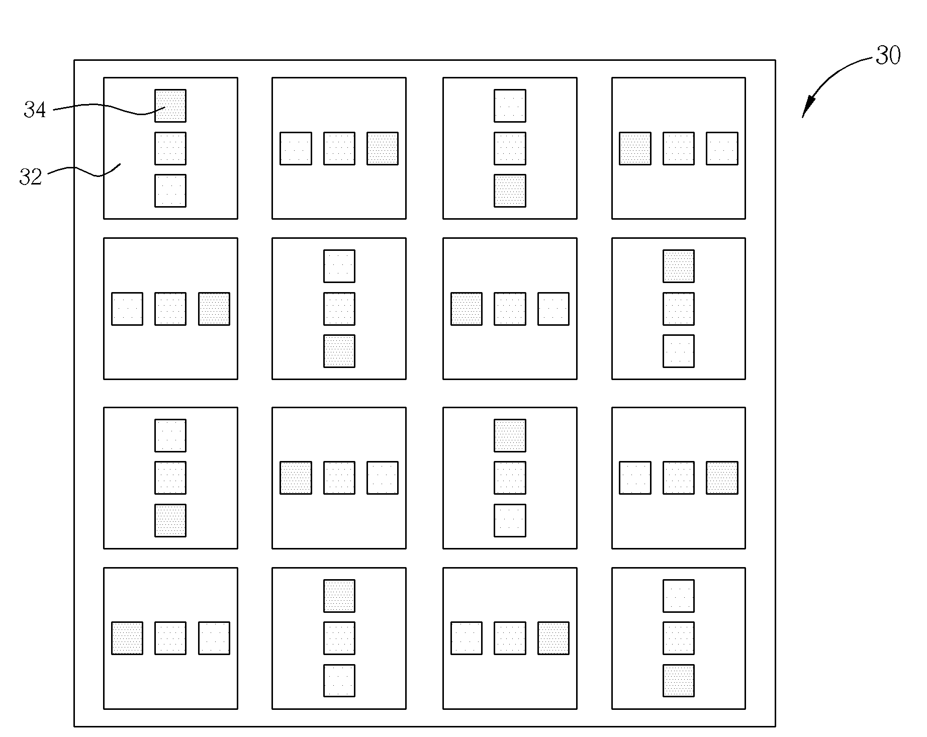
[0021]Please refer to FIG. 3. FIG. 3 is a perspective diagram illustrating an arrangement of light emitting diodes of a light emitting diode backlight unit according to a ...


PUM


Abstract

A light source for a backlight unit is disclosed. The light source includes a plurality of light emitting diode modules arranged in a manner corresponding to an array, in which each of the light emitting diode modules includes a plurality of light emitting diodes. The array includes a plurality of columns and rows. Preferably, the light emitting diodes of the light emitting diode module of any two adjacent columns are arranged in a different manner, and the light emitting diodes of the light emitting diode module of any two adjacent rows are arranged in a different manner.

Description

BACKGROUND OF THE INVENTION[0001]1. Field of the Invention[0002]The invention relates to a light emitting diode backlight unit, and more particularly, to an arrangement method of light emitting diodes within the light emitting diode backlight unit.[0003]2. Description of the Prior Art[0004]Liquid crystal displays are commonly utilized in various electronic products including cell phones, PDAs, and notebook computers. As the market demand for large-scale display panels continues to increase, liquid crystal displays having advantages such as small size and light weight have become widely popular. Due to the fact that the liquid crystal display itself does not illuminate, a backlight unit has to be installed under the liquid crystal display to provide an area light source for the liquid crystal display.[0005]Backlight units are commonly divided into two major categories: side-emitting type and direct type. Additionally, the area light source provided for the liquid crystal display is d...

Claims


Application Information

Patent Timeline
Patent Type & Authority Patents(United States)
IPC IPC(8): F21S13/14
CPCF21K9/00G02F1/133603G02F2001/133613F21Y2105/12G02F1/133613
Inventor PENG, CHUNGCHEN, CHIH-KUANGTSENG, SHIN-CHINLIN, YU-KAICHOU, SHEN-HONG
Owner AU OPTRONICS CORP
Why Eureka
Try Eureka