Self-excitation synchronous rectification driver

a rectification driver and self-excitation technology, applied in the direction of dc-dc conversion, climate sustainability, power conversion systems, etc., can solve problems such as abnormal voltag

Active Publication Date: 2009-03-03
SPI ELECTRONICS
View PDF11 Cites 13 Cited by
  • Summary
  • Abstract
  • Description
  • Claims
  • Application Information

AI Technical Summary

Benefits of technology

The solution effectively regulates the self-excitation frequency within a normal range, preventing abnormal voltage and ensuring stable operation by alternately turning on rectifier switches and limiting their working frequencies, thus maintaining circuit integrity during varying load conditions.

Problems solved by technology

Further, the latch unit has a period-limiting circuit to limit the highest frequency during the underload-shutdown stage lest the frequency of the synchronous rectification driver get out of control and abnormal voltage occur.

Method used


Image

  • Self-excitation synchronous rectification driver
  • Self-excitation synchronous rectification driver
  • Self-excitation synchronous rectification driver

Examples


Embodiment Construction

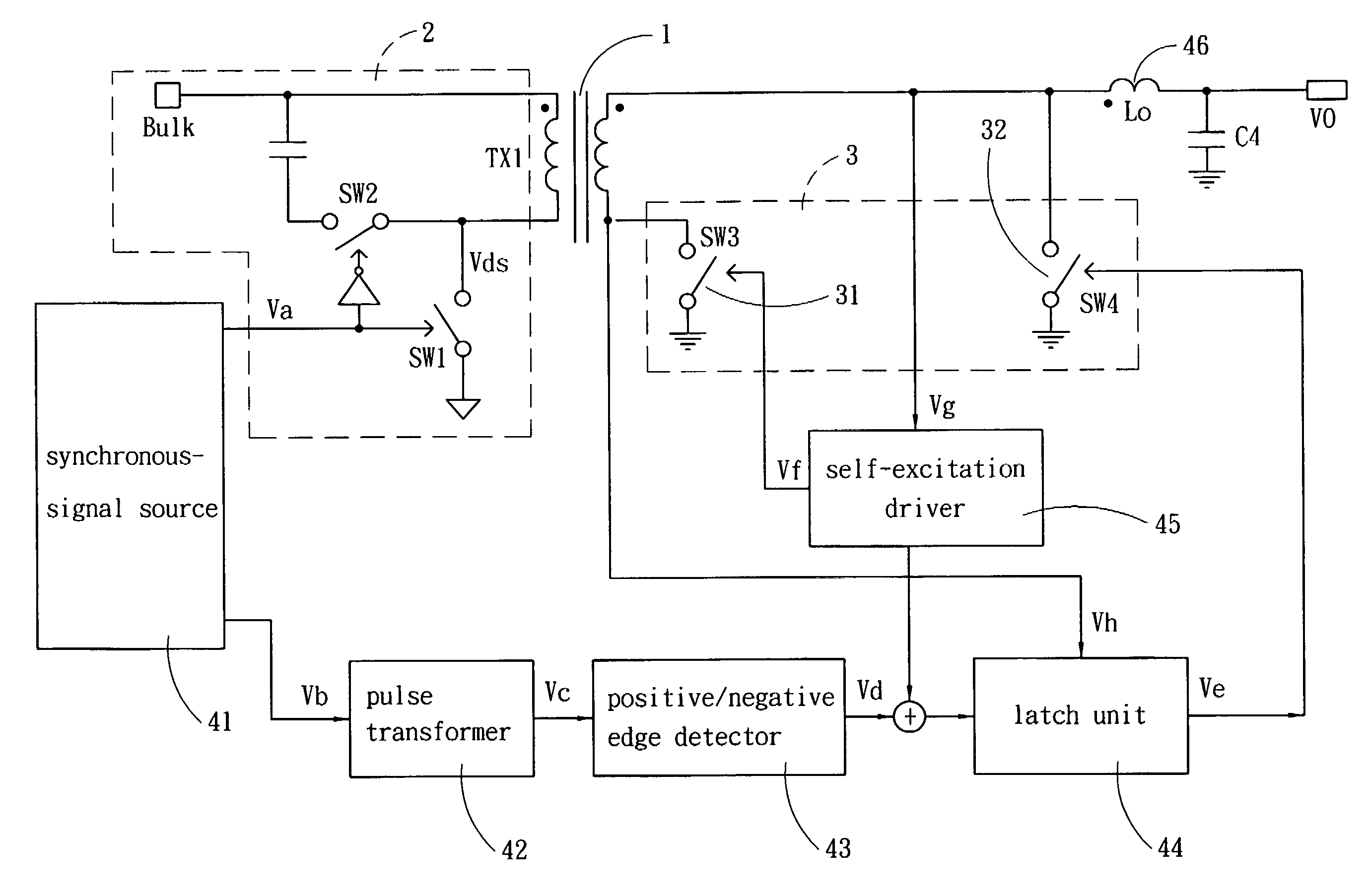
[0010]The present invention is a self-excitation synchronous rectification driver, which applies to a power supply. The power supply comprises a main transformer 1. The main transformer 1 further comprises a power driver unit 2 at the primary side and a rectification unit 3 at the secondary side. The power driver unit 2 has a primary driver switch SW1 and a secondary driver switch SW2. The rectification unit 3 has a first rectifier switch 31 and a second rectifier switch 32. The first and second rectifier switches 31 and 32 are controlled by the self-excitation synchronous rectification driver of the present invention. The self-excitation synchronous rectification driver of the present invention comprises a self-excitation coil 46, a self-excitation driver 45 used to drive the first rectifier switch 31, a synchronous-signal source 41 generating a synchronous signal, a pulse transformer 42, a positive / negative edge detector 43 used to detect the positive / negative edge of the synchron...


PUM


Abstract

The present invention discloses a self-excitation synchronous rectification driver, which comprises a self-excitation coil, a self-excitation driver, a synchronous-signal source, a pulse transformer, a positive / negative edge detector, and a latch unit. The synchronous-signal source generates a synchronous signal to attain an external synchronous function. When the frequency is abnormal, the first and second rectifier switches of the rectification unit of the power supply are forced to turn on or turn off. Thereby, the first and second rectifier switches can turn on alternately, and the first and second rectifier switches are limited to within the highest and lowest working frequencies during the zero-load stage or the shutdown stage. Thus, the frequency of the synchronous rectification driver is under control, and abnormal voltage will not occur.

Description

FIELD OF THE INVENTION[0001]The present invention relates to a self-excitation rectification driver, particularly to a rectification driver, which utilizes synchronous signals to make two rectifier switches turn on alternately and limit the working frequencies thereof.BACKGROUND OF THE INVENTION[0002]A power supply usually comprises a main power system and a standby power system. By a main transformer, the main power system is divided into a power driver unit at the primary side and a rectification unit at the secondary side. The rear end of the rectification unit is coupled to a voltage feedback unit 6 to correct the working period of the power driver unit. Refer to FIG. 1 for the circuit architecture of a conventional power supply. In the conventional power supply shown in FIG. 1, the power driver unit has a primary driver unit SW1, a secondary driver unit SW2 and a main transformer TX1. The rectification unit utilizes a self-excitation coil Lo to generate a self-excitation phenom...

Claims


Application Information

Patent Timeline
Patent Type & AuthorityPatents(United States)
IPC IPC(8): H02M3/335
CPCH02M3/33592Y02B70/1475Y02B70/10
InventorLIN, KUO-FANTSAI, CHIEN-LI
OwnerSPI ELECTRONICS