

Electromagnetic clutch
a technology of electromagnetic clutches and armatures, applied in the direction of mechanical actuated clutches, friction linings, couplings, etc., can solve the problems of increasing self-inductance, armature cannot be easily separated from the rotor, and the reduction of the weight of electromagnetic clutches and electric power consumption, so as to reduce the magnetomotive force required
- Summary
- Abstract
- Description
- Claims
- Application Information
AI Technical Summary
Benefits of technology
Problems solved by technology
Method used
Image

Examples
first embodiment
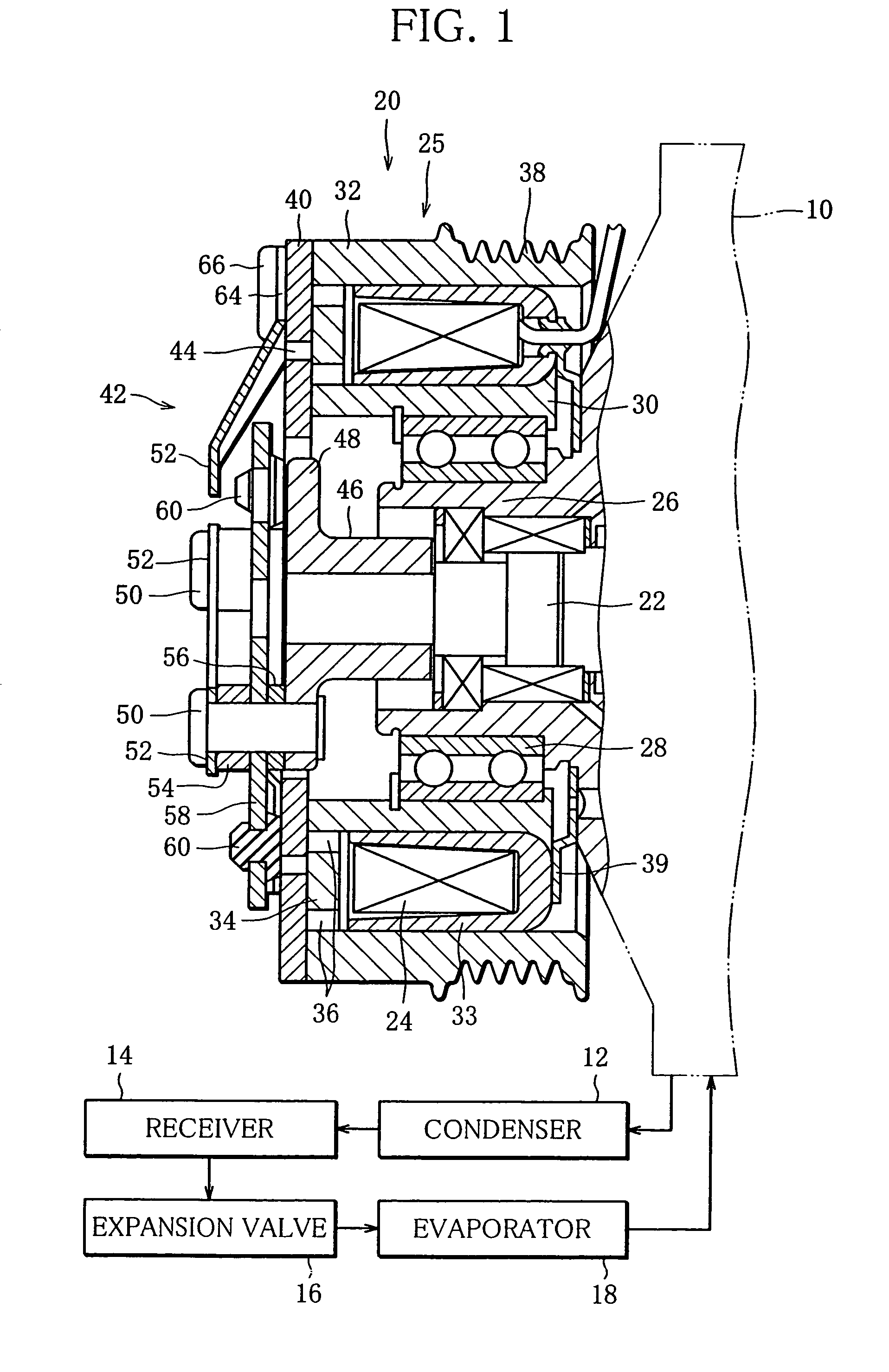
[0027]FIG. 1 shows a refrigeration circuit of an automotive air-conditioning system, and the refrigeration circuit has a refrigerant circulation line in which are arranged a compressor 10, a condenser 12, a receiver 14, an expansion valve 16 and an evaporator 18 in the order mentioned along the circulating direction of refrigerant. The compressor 10 is provided with an electromagnetic clutch 20 according to the invention, and the driving force from an engine (not shown) is transmitted intermittently through the electromagnetic clutch 20 to a main shaft 22 of the compressor 10. As the main shaft 22 rotates, a compression unit (not shown) of the compressor 10 is driven, whereby the refrigerant circulates through the refrigeration circuit. The compressor 10 may be either a scroll compressor or a swash plate compressor.
[0028]The electromagnetic clutch 20 has a rotor 25 which is rotatably supported through a ball bearing 28 by an end portion 26 of the housing of the compressor 10. The ma...
second embodiment
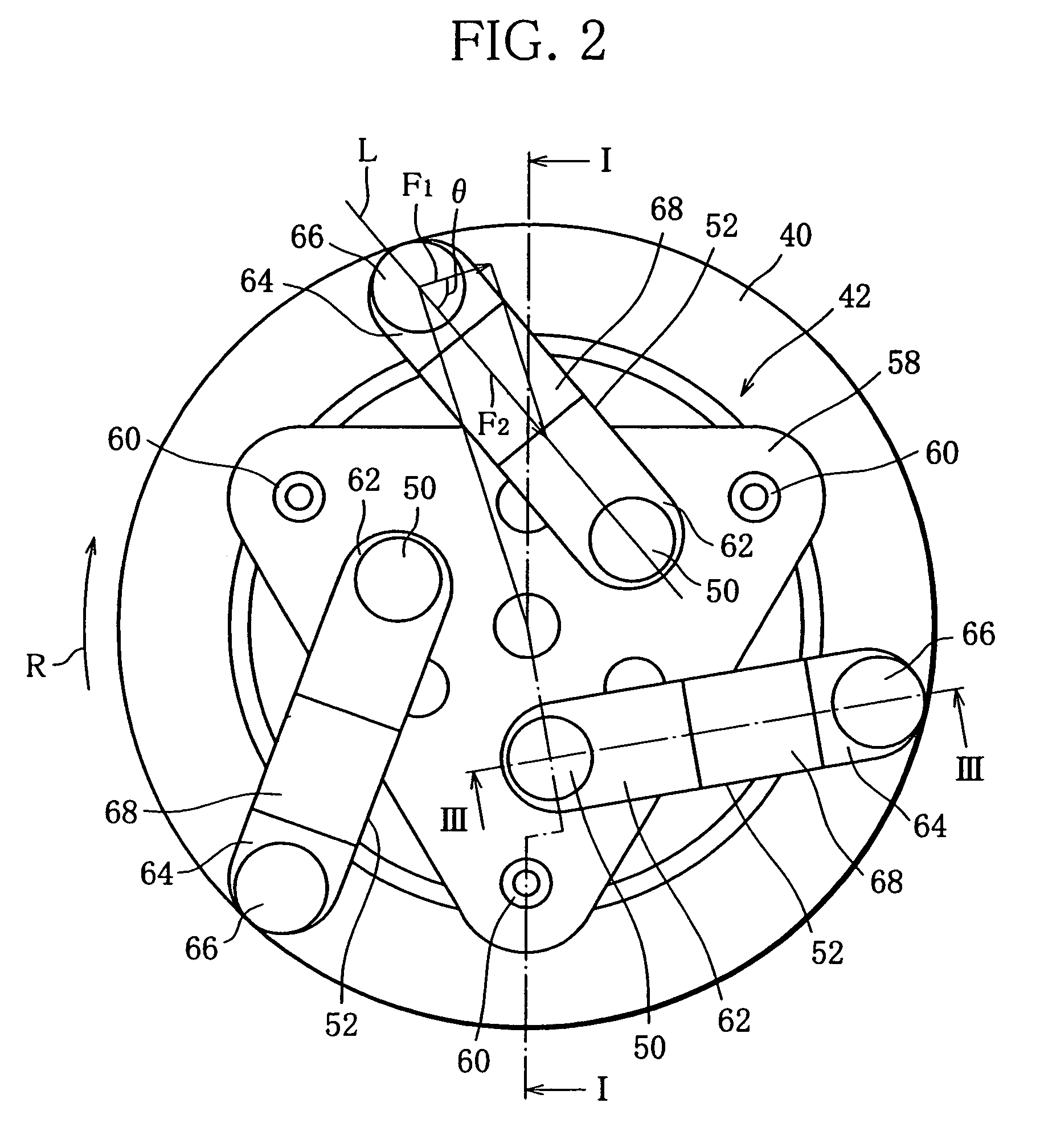
[0050]FIG. 5 shows the invention, and as illustrated, each leaf spring 52 may be replaced by two leaf springs 70 and 72 connected in series by a short rivet 74. In the illustrated embodiment, both of the leaf springs 70 and 72 have inclined portions 76 and 78, respectively, but at least one of the two may have an inclined portion. Also, one of the two members 70 and 72 need not be a leaf spring and may be a rigid member.
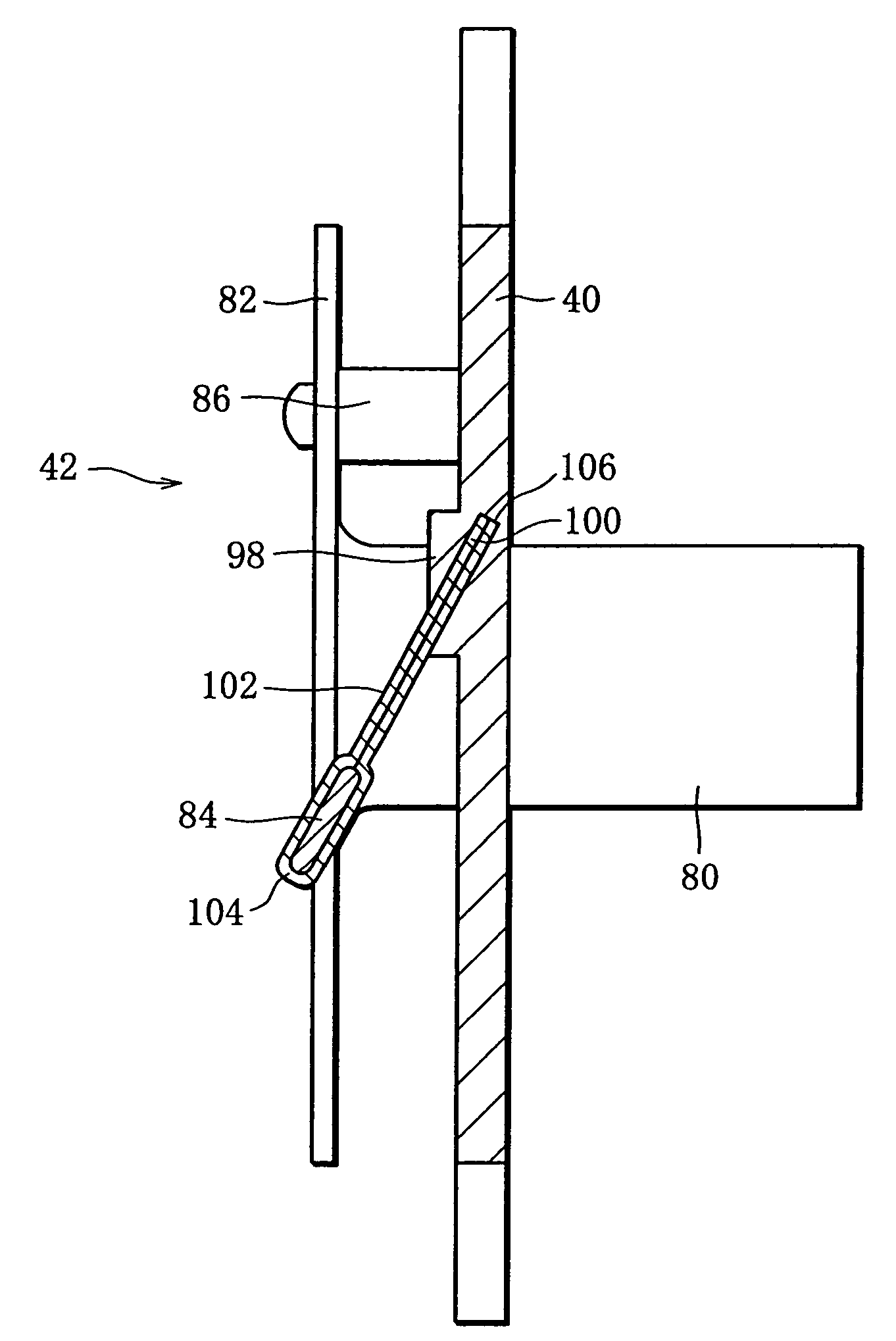
[0051]FIGS. 6 and 7 illustrate a third embodiment of the invention. In this embodiment, a sleeve 80 is longer than the sleeve 46 of the first embodiment, and a flange 82 is located farther from the armature 40 than the counterpart of the first embodiment. The flange 82 is in the form of a disk and has three mounting portions 84 protruding integrally from a peripheral edge thereof and spaced at equal intervals in a circumferential direction thereof. Each mounting portion 84, which is rectangular in shape, extends radially outward from the flange 82 and has a proximal ...
third embodiment
[0056]In this embodiment, each leaf spring 102 is bent or folded at an inner end 104 thereof, thus forming a double leaf spring. The folded inner end portion 104 clamps the corresponding mounting portion 84 therein to be connected to the flange 82. Each leaf spring 102 has a double outer end 106 which is inserted into the corresponding groove 100, as in the
PUM
 Abstract
Description
Claims
Application Information