Radio communication system, device and method for radio communication, and computer program

a radio communication and computer program technology, applied in the field of radio communication systems, can solve the problems of complicated cable routing, inconvenient lan, and difficulty in readily setting up a network, and achieve the effect of less delay

Active Publication Date: 2009-06-09
SONY CORP
View PDF17 Cites 18 Cited by
  • Summary
  • Abstract
  • Description
  • Claims
  • Application Information

AI Technical Summary

Benefits of technology

[0023]An object of the present invention is to provide an excellent radio communication system, device and method for radio communication, and computer p

Problems solved by technology

In this case, line installation work is required and this makes it difficult to readily set up a network and complicates cable routing.
Even if LAN is set up, the moving ranges of equipment are limited by cable length and this makes the LAN inconvenient.
As a result, inputted information signals have only power at the noise level or lower levels in each frequency domain.
Meanwhile, trains of impulse signals used in the UWB radio communication method do not have a specific frequency carrier and carrier sense is difficult to perform thereon.
Therefore, if the UWB radio communication method is applied as the PHY layer of IEEE802.15.3, a problem arises.
Since there is not a

Method used


Image

  • Radio communication system, device and method for radio communication, and computer program
  • Radio communication system, device and method for radio communication, and computer program
  • Radio communication system, device and method for radio communication, and computer program

Examples


first embodiment

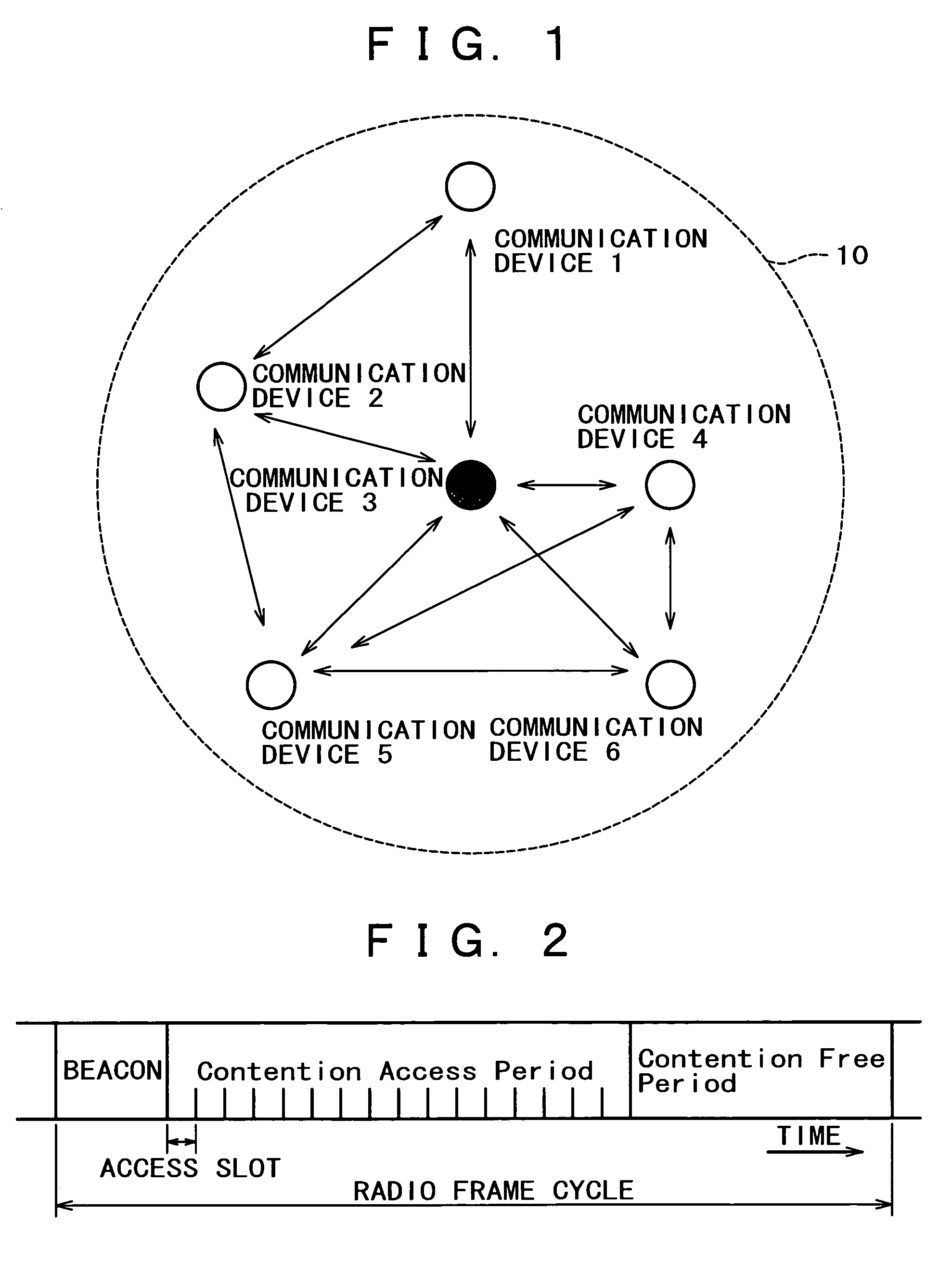
[0097]FIG. 1 schematically illustrates the constitution of a small-scale wireless network in the first embodiment of the present invention.

[0098]In the illustrated wireless network, one radio communication device 3 operates as the control station. The wireless network is set up within the communication range 10 of the communication device 3 based on, for example, the UWB radio communication method. Within the communication range 10, a plurality of radio communication devices 1, 2, 4, 5, and 6 can participate in the wireless network and can conduct radio data communication under the control of the radio communication device 3.

[0099]In FIG. 1, the double-headed arrows indicate that one communication device and another that can directly communicate with each other are in such a state that the communication devices can freely exchange information with each other. More specifically, the communication device 1 can communicate with the communication devices 2 and 3, and the communication d...

second embodiment

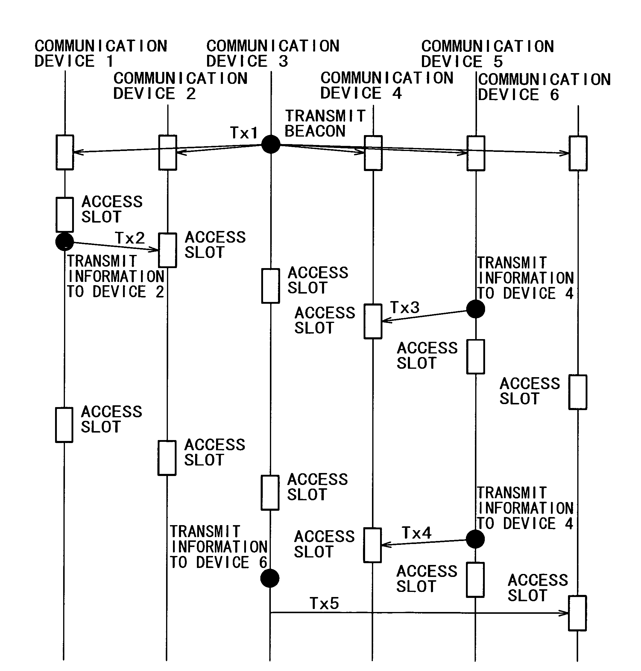
[0161]In the above-mentioned first embodiment, reception slots for the individual radio communication devices in a wireless network to receive information destined for themselves are determined in advance. Reception processing is performed only at the slots. Thus, data transmission / reception processing is simplified. Further, the radio communication devices need not keep on waiting for reception, and the power consumption of the devices is reduced.

[0162]However, when information transmission is made without specifying any destination as in broadcasting, the same information is must be repeatedly transmitted at reception slots for all the radio communication devices. This is wasteful.

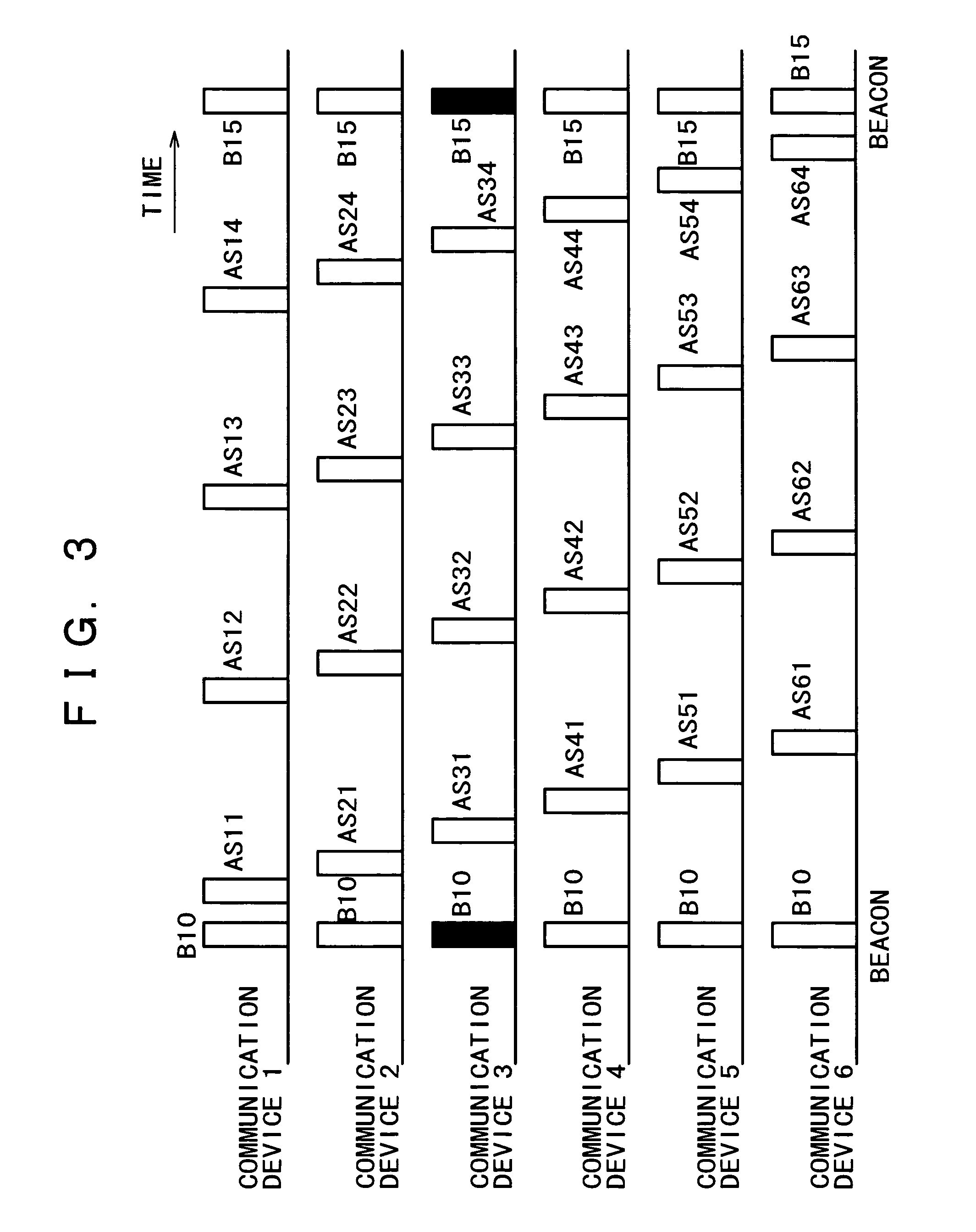
[0163]The second embodiment of the present invention is intended to cope with such a problem associated with broadcasting. In addition to access slots provided in contention access periods (or contention free periods) and allocated to each radio communication device, as illustrated in FIG. 3, other acces...


PUM


Abstract

A radio communication device that manages a network defines a predetermined transmission frame cycle, allocates in the frame specific access slots as timing with which the individual radio communication devices in the network concerned receive a transmission, puts the information of the allocation in a beacon signal, and transmits the signal. Each radio communication device performs a receiving operation at access slots specific to the device itself defined by the beacon signal. When information transmission is made between arbitrary communication devices in the network, access slots for the device that is to receive the information are used.

Description

TECHNICAL FIELD[0001]The present invention in general relates to a radio communication system, a device and a method for radio communication, and a computer program wherein communication is conducted among a plurality of radio stations. The present invention more particularly relates to a radio communication system wherein a network is set up with a specific transmission frame cycle, and a device and a method for radio communication and a computer program which work in such a wireless network.[0002]In more detail, the present invention relates to a radio communication system, a device and a method for radio communication, and a computer program wherein asynchronous communication is conducted with less delay in a wireless network which operates with a specific transmission frame cycle. The present invention more particularly relates to a radio communication system, a device and a method for radio communication, and a computer program wherein reception processing and management of inf...

Claims


Application Information

Patent Timeline
IPC IPC(8): H04B7/212H04B1/7163H04J13/00H04L12/28H04W16/02H04W48/12H04W48/16H04W72/04H04W74/04H04W74/08H04W84/12H04W84/20
CPCH04W48/12H04W72/0446H04W48/16H04W74/006H04L12/28
Inventor SUGAYA, SHIGERU
Owner SONY CORP
Why Eureka
Try Eureka