Tag tape and tag label tape with print

a technology of tag tape and label tape, which is applied in the direction of burglar alarm mechanical actuation, instruments, transportation and packaging, etc., can solve the problems of difficult to perform, more prone to wrinkles in respective portions of tag tape,

Active Publication Date: 2010-02-02
BROTHER KOGYO KK
View PDF5 Cites 5 Cited by
  • Summary
  • Abstract
  • Description
  • Claims
  • Application Information

AI Technical Summary

Benefits of technology

[0012]In the case where the tag tape is formed by sandwiching the plurality of RFID circuit elements by the first tape medium and the second tape medium each having a substantially tape-like configuration, at the location of the tag tape where each RFID circuit element is arranged, the first tape medium and the second tape medium sandwich the RFID circuit element therebetween and hence are extended and bent to both sides in the thickness dimension so as to detour around the RFID circuit element, resulting in an increase in the thickness dimension of the tape as a whole as compared with the locations of the tag tape where no RFID circuit element is arranged. As the bend required to detour around the RFID circuit element becomes larger, or as the thickness dimension of the tape as a whole decreases, wrinkles are more liable to develop in respective portions of the tag tape. In the first aspect of the present application, by setting the ratio of the sum x of the thickness dimensions of the first and second tape media to the thickness dimension y of the RFID circuit element to be 0.8 or more to make the first and second tape media thick relative to the RFID circuit element, the influence of the sandwiching of the RFID circuit element at the arrangement location of the RFID circuit element can be reduced to thereby prevent the formation of wrinkles.
[0038]In this way, in the tenth aspect of the present application, the ratio of the sum (α+β) of the sum total β of the thickness dimensions of the first and second tape media, and the thickness dimension α of the print-receiving tape to the thickness dimension γ of the RFID circuit element is set to be within an appropriate range, thereby making it possible to realize a tag label tape with print in which wrinkles do not easily form and which can be actually used in practice.

Problems solved by technology

As the bend required to detour around the RFID circuit element becomes larger, or as the thickness dimension of the tape as a whole decreases, wrinkles are more liable to develop in respective portions of the tag tape.
Accordingly, when the overall thickness of the tape becomes too large, the rigidity becomes so high that it is difficult to perform the above-mentioned operations such as winding of the tag tape into a roll, deflection of the feed path, and the like.

Method used


Image

  • Tag tape and tag label tape with print
  • Tag tape and tag label tape with print
  • Tag tape and tag label tape with print

Examples


Embodiment Construction

[0072]A tag tape and a tag tape with print according to an embodiment of the present disclosure will be described below with reference to the drawings.

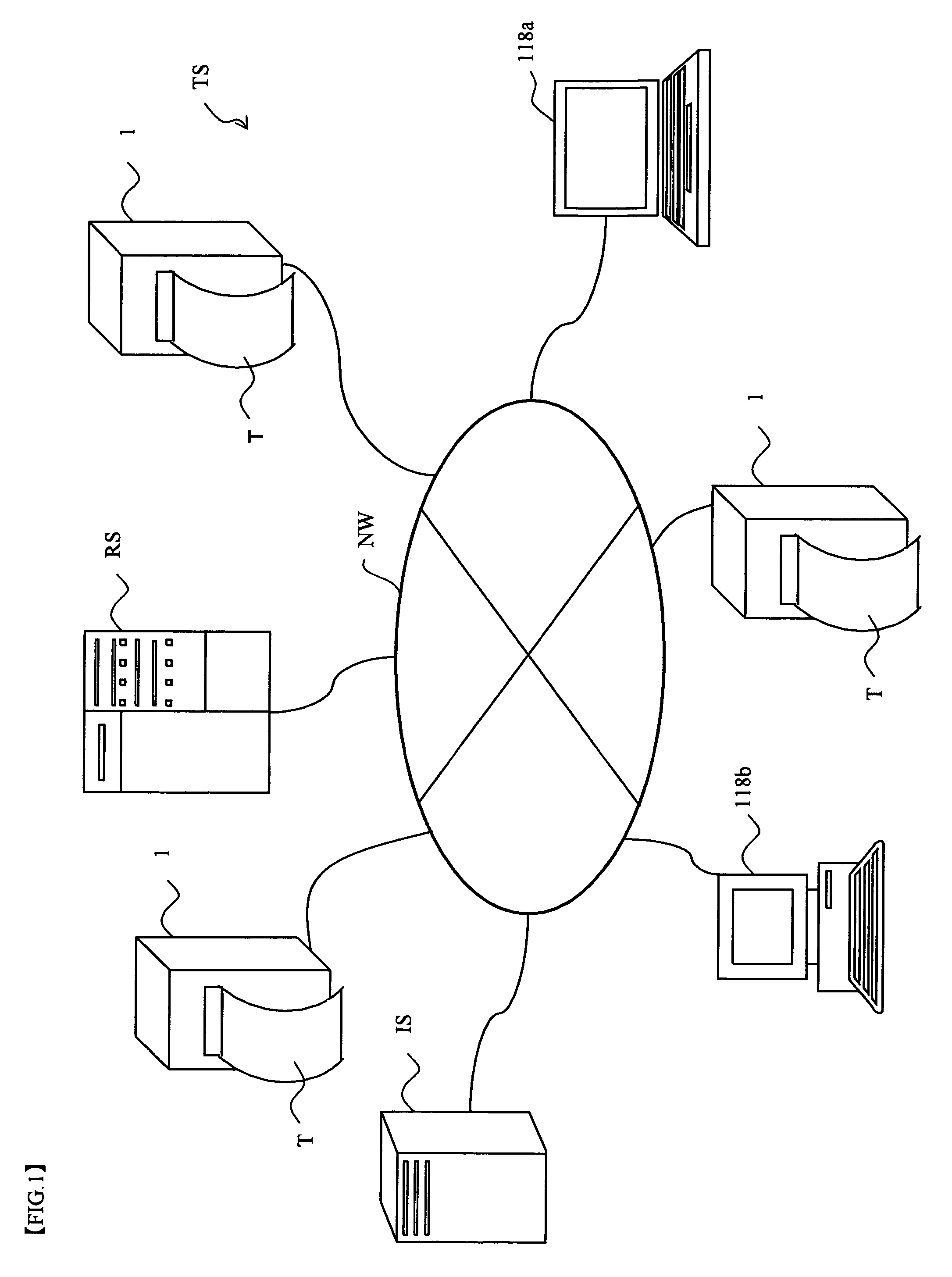
[0073]FIG. 1 is a system diagram showing an RFID tag manufacturing system equipped with a tag-label producing device for producing a tag label using the tag tape according to an embodiment of the present disclosure.

[0074]In an RFID tag manufacturing system TS shown in FIG. 1, a tag-label producing device 1 is connected to a route server RS, a plurality of information servers IS, a terminal 118a, and a general purpose computer 118b via a wired or wireless communication line NW. It should be noted that in the following description, the terminal 118a and the general purpose computer 118b will be generically referred to simply as “PC 118” as appropriate.

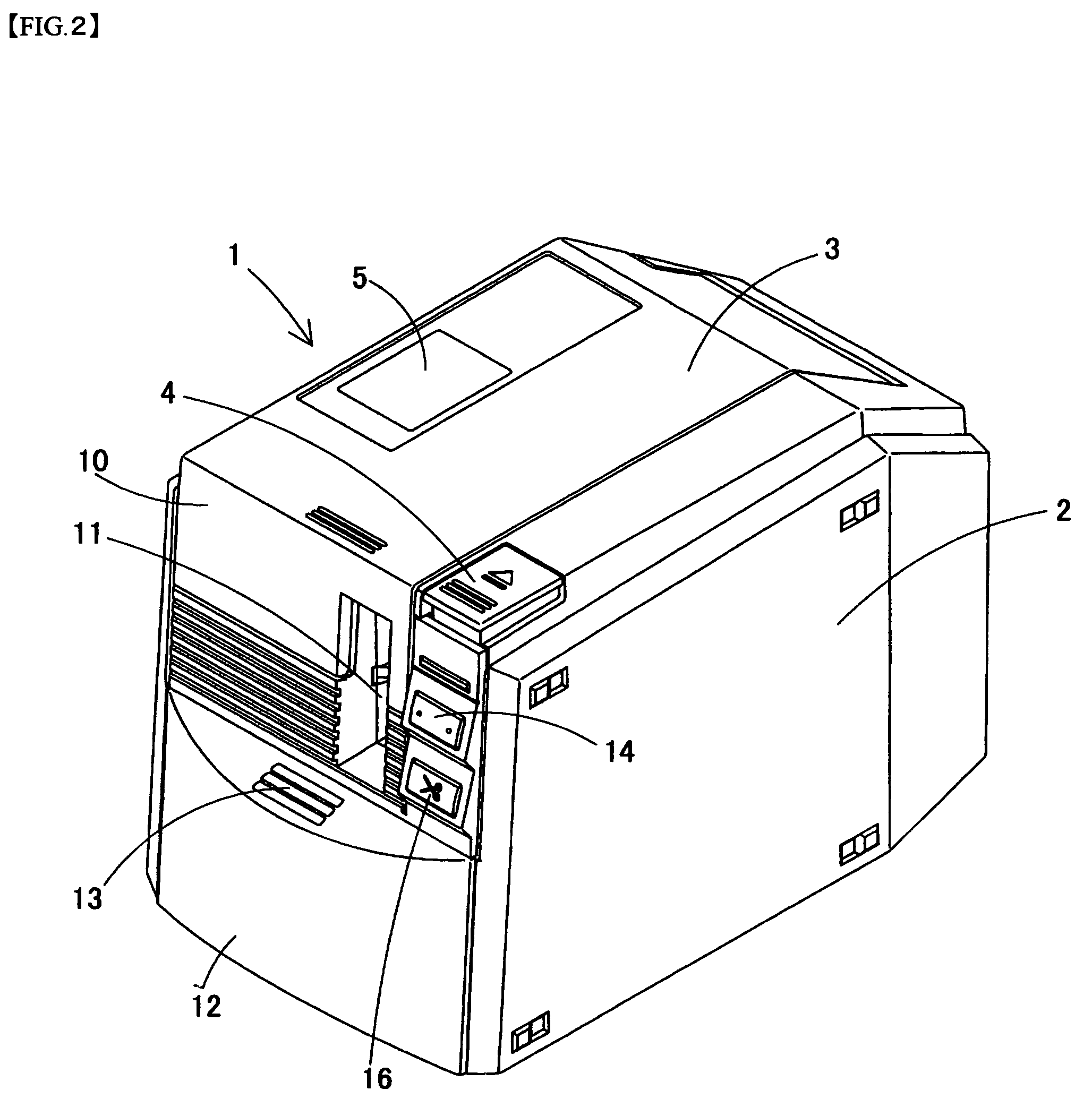
[0075]FIG. 2 is a perspective view showing the overall construction of the above-mentioned tag-label producing device 1.

[0076]In FIG. 2, the tag-label producing device 1 is connected to th...


PUM


Abstract

A base tape includes: a plurality of RFID circuit elements each including an IC circuit part for storing information and a loop antenna connected to the IC circuit part; and an adhesive layer, a base film, an adhesive layer, an adhesive layer, and a separation sheet that are arranged so as to sandwich each of the RFID circuit elements from both sides in the thickness direction. The base tape is formed such that the ratio c of the sum of the thickness dimensions of the adhesive layer, base film, adhesive layer, adhesive layer, and separation sheet to the thickness dimension of the RFID circuit element is 0.8≦c≦9.8.

Description

CROSS-REFERENCE TO RELATED APPLICATIONS[0001]This application claims priority from JP 2006-006302, filed Jan. 13, 2006, the contents of which are hereby incorporated by reference.BACKGROUND OF THE INVENTION[0002]1. Field of the Invention[0003]The present disclosure relates to a tag tape having RFID circuit elements that store information, and a tag label tape with print having the tag tape and a print-receiving tape on which predetermined printing is performed.[0004]2. Description of the Related Art[0005]An RFID (Radio Frequency Identification) system is known which performs transmission / reception of information in a non-contact manner (by an electromagnetic coupling method, electromagnetic induction method, or electromagnetic radiation method or the like using a coil) with respect to an RFID circuit element that stores information.[0006]For example, as an example of a tag-label producing device (RFID label producing device) that produces an RFID label by performing transmission / rec...

Claims


Application Information

Patent Timeline
Patent Type & Authority Patents(United States)
IPC IPC(8): G08B13/14
CPCG06K19/07718G06K19/07749
Inventor NAGAE, TSUYOSHIYAMAGUCHI, KOSHIROKATO, SHIGEKI
Owner BROTHER KOGYO KK
Why Eureka
Try Eureka