Concrete building system and method

a technology of building system and concrete, applied in the field of concrete housing, can solve the problems of substantial thermal leakage of homes and apartments, and difficult marketability of concrete built homes in colder areas, and achieve the effects of reducing building costs, eliminating all framing costs, and being convenient to er

a technology of building system and concrete, applied in the field of concrete housing, can solve the problems of substantial thermal leakage of homes and apartments, and difficult marketability of concrete built homes in colder areas, and achieve the effects of reducing building costs, eliminating all framing costs, and being convenient to er

US7661231B2Inactive Publication Date: 2010-02-16DALTON MICHAEL E

Image

  • Concrete building system and method
  • Concrete building system and method
  • Concrete building system and method

Examples


Embodiment Construction

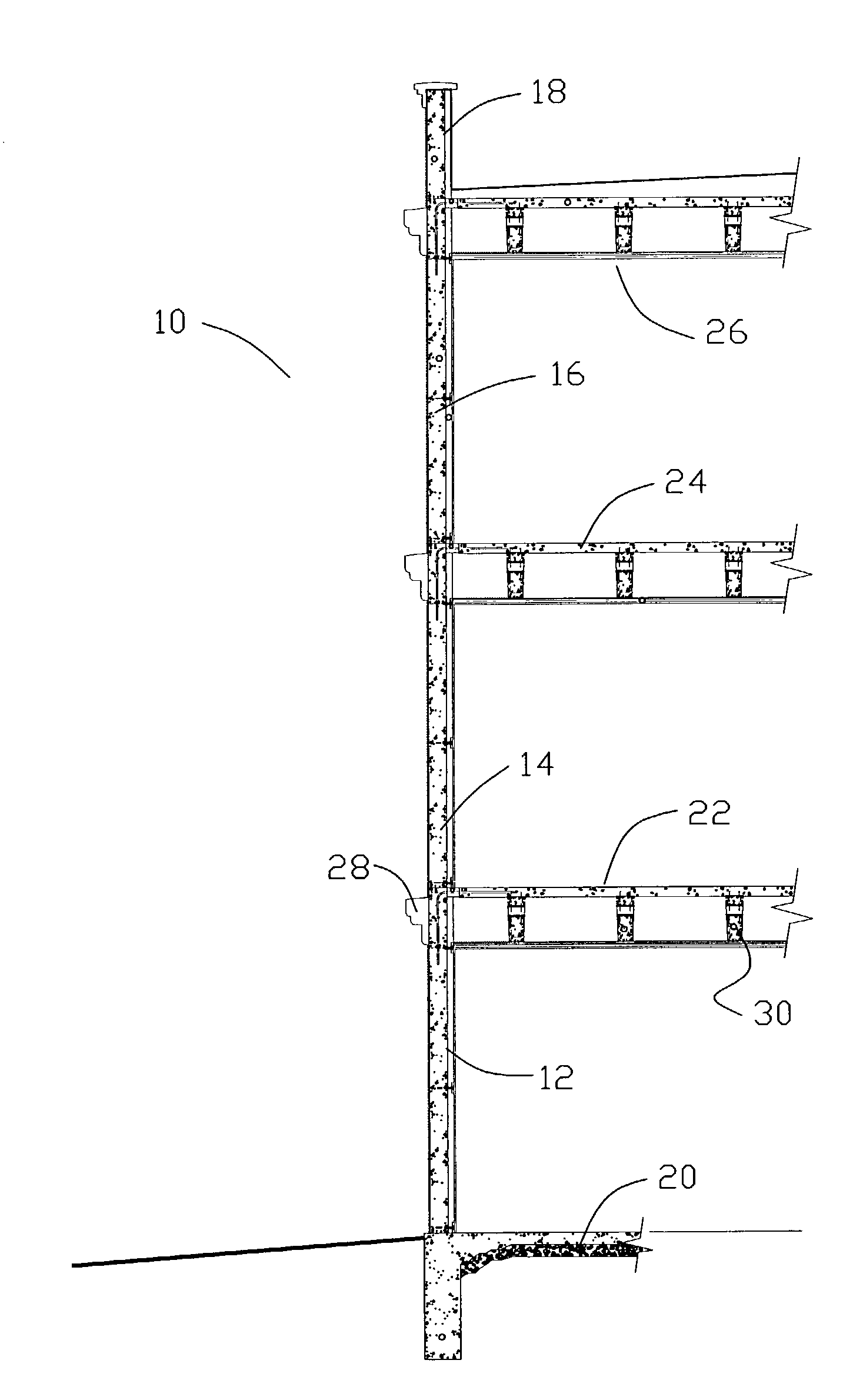
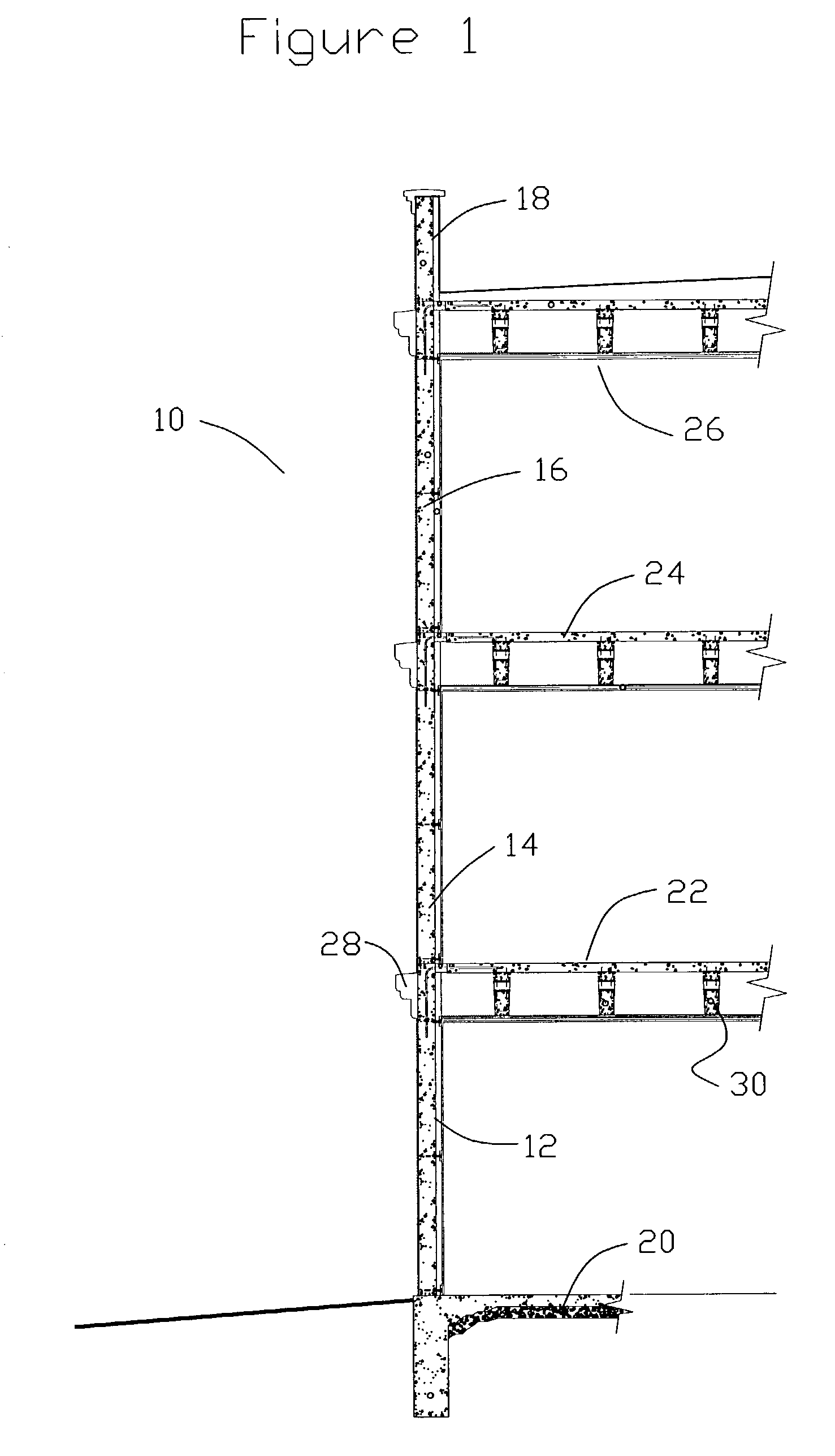
[0020]FIG. 1 shows a partial cross sectional view of the building system (10). In this application there is a concrete wall composed of sections (12,14, and 16) each section defining a level of the building. A parapet wall (18) is formed at the top of the building. There is a first floor (20), two upper floors (22 and 24) and a roof (26). The exterior of the building includes a decorative molding (28) that is mounted on anchors (See FIG. 8) cast in the wall. In this view the concrete joists (30) are shown in cross section.

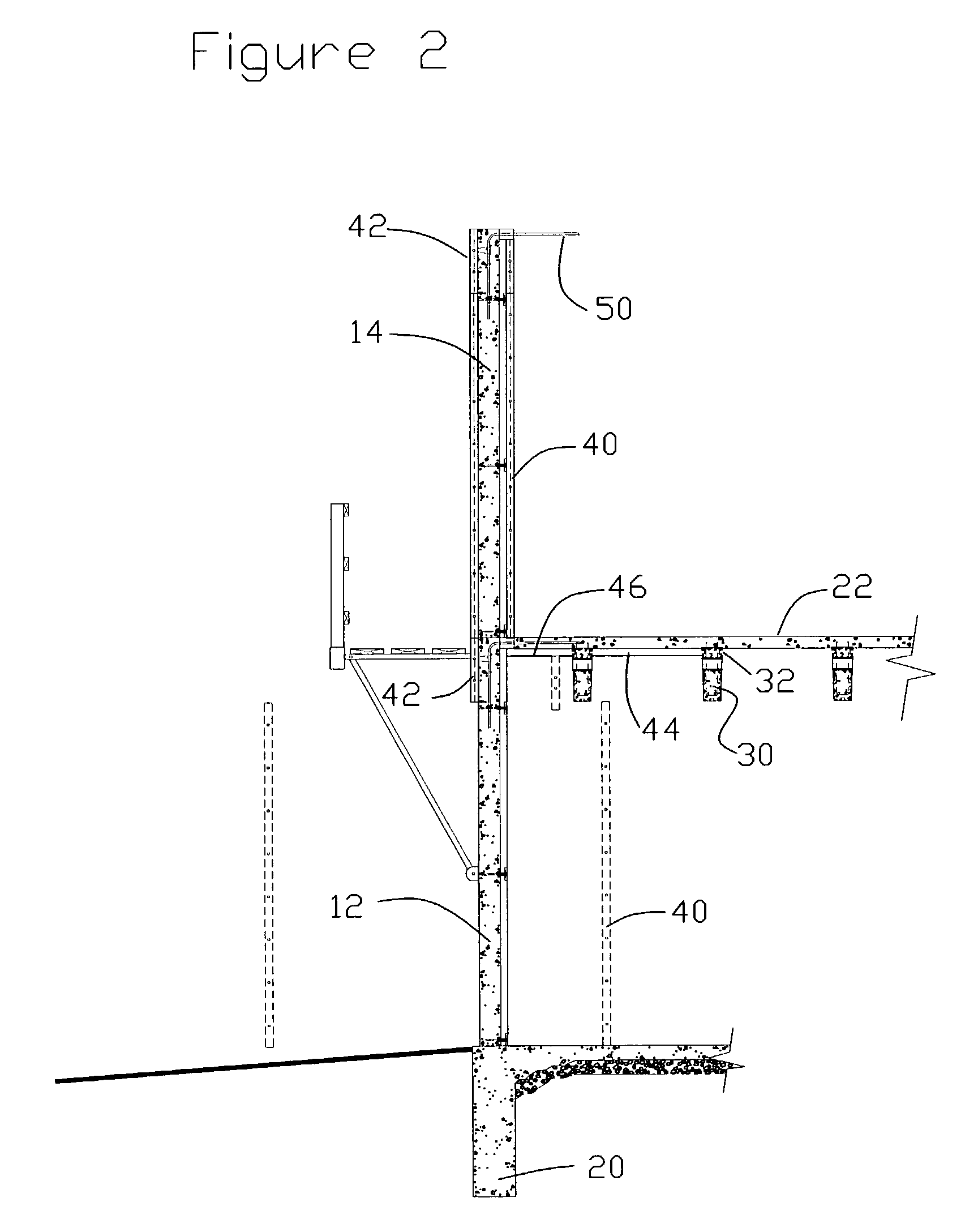
[0021]FIG. 2 shows some of the detail of the construction techniques. In FIG. 2 the first and second walls (12 and 14) as well as the first floor (20) and second floor (22) have been formed. Standard hand set aluminum concrete forms (40, 42 and 44 and 48) are shown. Each wall section requires 4 sets of forms two large forms (40) one on the inside and one on the outside, also one small cap form (42) set on top of the exterior form (40), and a slightly shorter cap fo...


PUM


Abstract

A system of building concrete homes and apartment buildings. The system creates a structure that is well insulated and that is very practical and economical to build. The system uses standard components such as wall ties, concrete forms, rigid foam insulation, and concrete, all of which are readily available in the market today. The system creates a building that is insulated and thermally broken at its structural connections such that use in temperate and colder climates is possible. Presently concrete construction finds only limited use for the construction of single family and multi-family housing. The system is economical to construct when compared to wood frame housing.

Description

BACKGROUND OF THE INVENTION[0001]In the concrete housing industry it is common to build multi-unit apartments and homes in warmer environments. But current concrete construction techniques have made concrete built homes more difficult to market in colder areas. It is common practice to use rigid foam insulation to improve the thermal performance of concrete homes and apartments. In some cases the foam is added to the concrete wall after it is cast, but it is also common to use the foam as part of the form when the concrete is cast and to leave the foam in place after the concrete is cast. But current concrete construction techniques lead to homes and apartments that have substantial thermal leaks built in.[0002]A number of variations have been tried to effectively insulate a concrete building for cold areas. These attempts have so far failed to result in a marketable system. Often the proposed solutions have not been practical or cost effective, producing a building system that eith...

Claims


Application Information

Patent Timeline
16 Feb 2010
Publication
US7661231B2
IPC
E04H12/12; E04B1/16; E04B5/04; E04B5/26; E04B5/43; E04C3/26; E04C3/34
CPC
E04B1/161; E04B5/046; E04B5/265; E04B5/43; E04C3/26; E04C3/34
Inventors
DALTON, MICHAEL E.