Stand for display device

a display device and stand technology, applied in the field of stand for display devices, can solve the problems of restricting the pivoting angle, unable to pivot any further, and the display device cannot be pivoted further, so as to achieve the effect of convenient pivoting and adjusting the viewing angle of the display devi

Inactive Publication Date: 2010-04-20
LG ELECTRONICS INC
View PDF10 Cites 6 Cited by
  • Summary
  • Abstract
  • Description
  • Claims
  • Application Information

AI Technical Summary

Benefits of technology

[0009]An object of the present invention is to provide a stand for a display device that allows maximum use of its pivoting angle to the left and right.
[0010]Another object of the present invention is to provide a stand for a display device that is capable of translation movement to the left and right, so that adjusting of the viewing angle of the display device can be increased.
[0011]A further object of the present invention is to provide a stand for a display device that allows a user to more conveniently pivot the display device to the left and right.
[0016]The stand for the display device according to the present invention allows the viewing angle of the display device to be adjusted more widely—especially when there is a restriction imposed on the pivoting angle of the display device—to increase a user's convenience.

Problems solved by technology

In narrow interior spaces, a display device must often be positioned closely against a wall, so that the degree that it can pivot is restricted.
That is, when the display device is pivoted, the edges thereof come into contact with the wall, so that even when the pivoting angle of the hinge allows for further pivoting, the display device cannot be pivoted further until it is moved a certain distance forward from the wall.
Thus, when it is not possible to move the display device forward in its entirety, it cannot be pivoted any further.
Accordingly, a user cannot further adjust the viewing angle of the display device, and will not be able to see a clear picture from his / her position to a side of the display device.

Method used


Image

  • Stand for display device
  • Stand for display device
  • Stand for display device

Examples


first embodiment

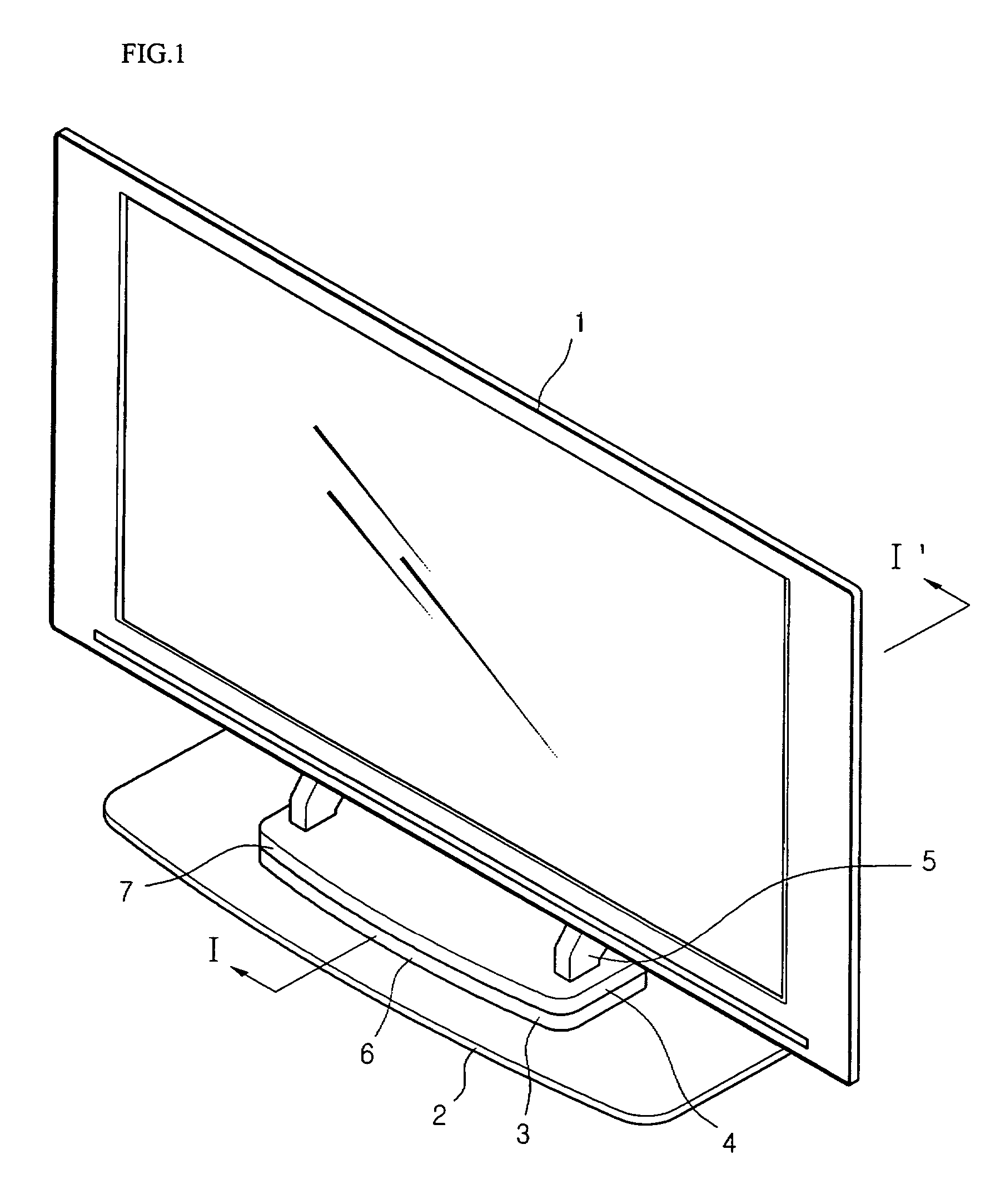
[0034]FIG. 1 is a perspective view of a stand for a display device according to the first embodiment of the present invention.

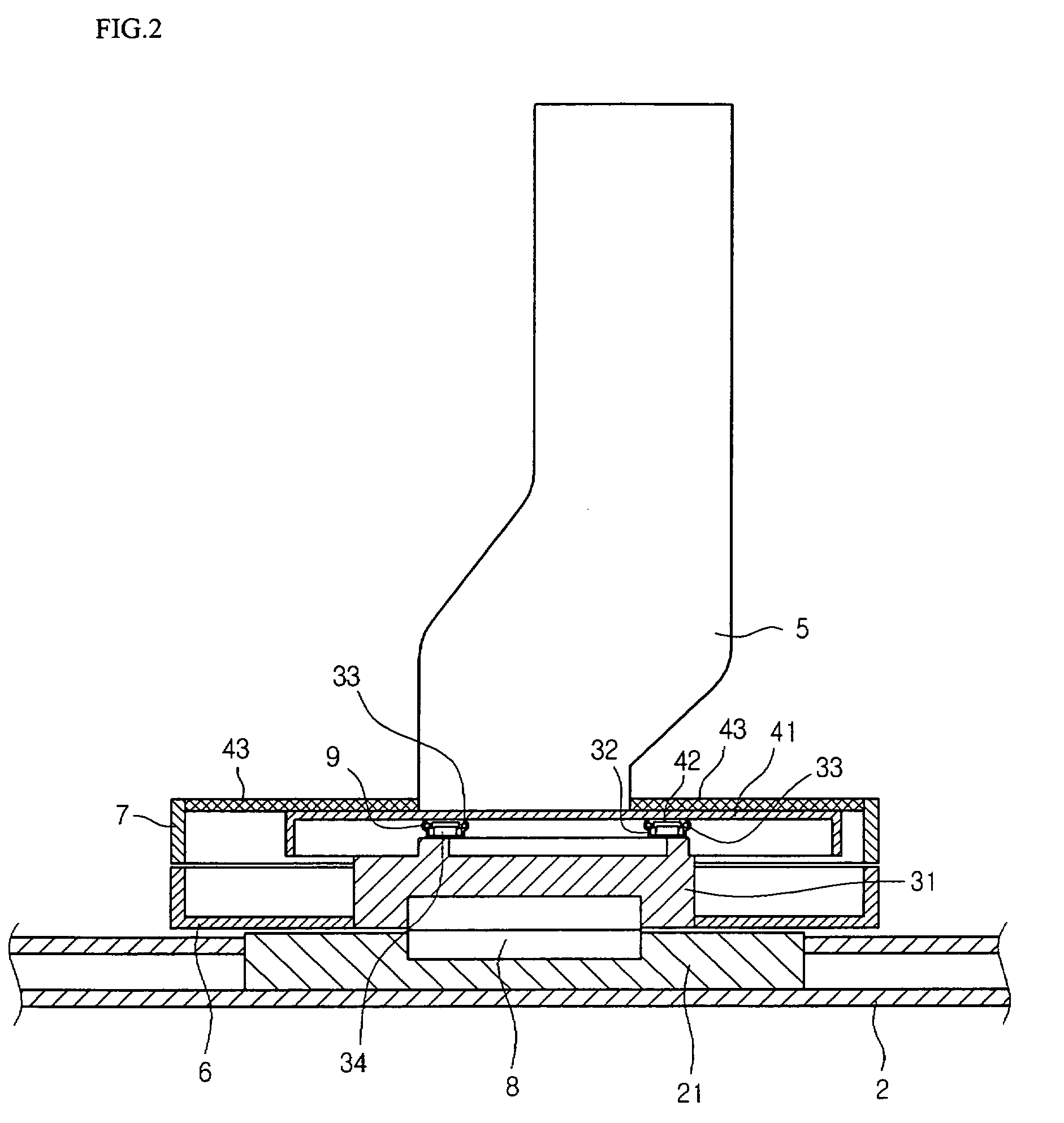
[0035]Referring to FIG. 1, a stand for a display device according to the present invention includes a display device 1, a supporting stand 5 supporting the display device 1 at a bottom thereof, a movable unit 4 disposed below the supporting stand 5, a fixed unit 3 disposed below the movable unit 4, and a base 2 for supporting the weight of the display device 1 while preventing it from falling over. An upper housing 7 is provided on the outside of the movable unit 4, and a lower housing 6 is provided on the outside of the fixed unit 3. The housings 6 and 7 form the exteriors of the movable unit 4 and fixed unit 3.

[0036]The movable unit 4 and the fixed unit 3 pivot together. However, when the display device 1 is translated laterally, the fixed unit 3 remains fixed, while the movable unit 4 moves laterally. Thus, the fixed unit 3 only pivots, while the movable u...

second embodiment

[0052]In the first embodiment, the pivoting angle enabling a view to comfortably view the display, can be increased without needs to move the entire display device. However, a user must apply a force for pivoting the display device over a certain duration, and push the display device laterally after bumping the display device on the surface of the wall. In other words, the direction of force applied to the display device must be changed, depending on the situation. Thus, if a user is not familiar with using the stand, the user may not be able to fully exploit its functions.

[0053]In order to solve these problems, a second embodiment is proposed.

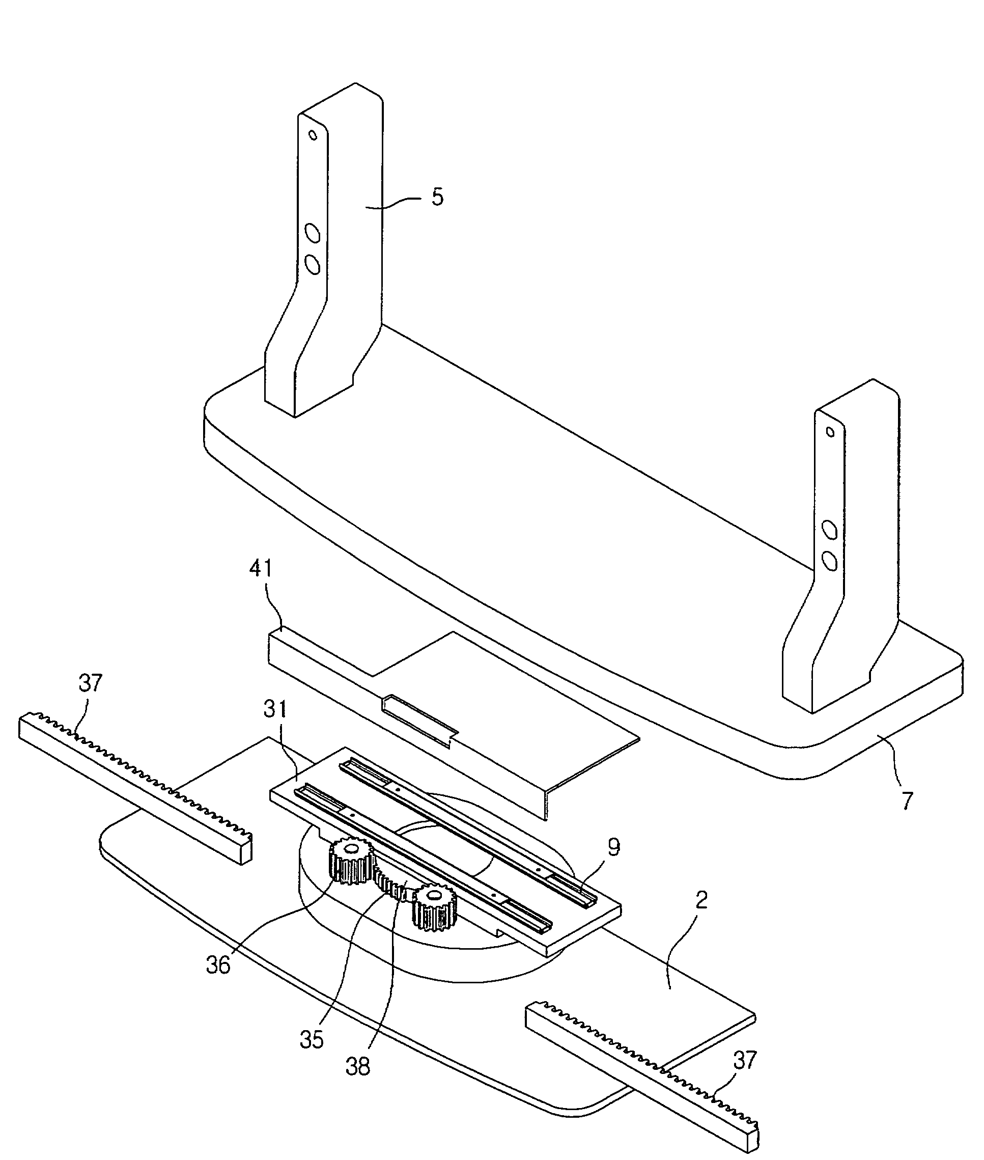
[0054]FIG. 7 is a sectional view of a stand according to the second embodiment of the present invention, FIG. 8 is an exploded perspective view of a movable unit, fixed unit, and their surrounding structure according to the second embodiment of the present invention, and FIG. 9 is an enlarged, exploded perspective view of the lower portion of ...

third embodiment

[0066]According to the second embodiment, a user need only to pivot the display device in a pivoting direction to achieve both pivoting and translation of the display device. However, in order to achieve simultaneous pivoting and translation, considerable force needs to be exerted, so that the product is unsuitable for seniors. Furthermore, over prolonged use of the device, foreign substances may lodge therein and discrepancies in tolerances may arise, causing the above task to be more arduous.

[0067]To overcome this problem, a third embodiment is put forth.

[0068]FIG. 13 is a perspective view of a stand according to the third embodiment of the present invention, and FIG. 14 is a sectional view of the stand in FIG. 13 taken along line II-II′. In the description of the third embodiment, components that have already been described in the first and second embodiments and have the same reference numbers will be deemed described herein.

[0069]Referring to FIG. 13, a position sensor 100 is f...


PUM


Abstract

A stand for a display device is provided. The stand prevents a viewer located at a side of the display from experiencing the problems of a narrow viewing angle by allowing the display device to be pivoted in a wide angle without interference from a wall behind the device. The stand includes a base, a swivel hinge, a fixed unit, a telescopic unit, and a movable unit. The swivel hinge is fixed to the base. The fixed unit is rotatably fixed to the swivel hinge. The telescopic unit includes one member fixed to the fixed unit. The movable unit, to which the other member of the telescopic unit is fixed, is capable of being translated in left and right directions of the base and being rotated.

Description

BACKGROUND OF THE INVENTION[0001]1. Field of the Invention[0002]The present invention relates to a stand for a display device, and more particularly, to a stand for a display device that increases convenience for viewers viewing the display device from a side thereof, by allowing a lateral translation of the display device to increase the pivoting angle of the display.[0003]2. Description of the Related Art[0004]A display device according to the related art is divided into wall and floor mounted displays. The present invention relates mostly to the floor-mounted type of display.[0005]A floor-mounted stand is provided to support a flat screen display device at the bottom thereof, so that the display device may be viewed from the front thereof. Also, a user located to one side of the display can pivot the display device to a side in order to adjust the viewing angle of the display device. For this purpose, the stand usually has a built-in hinge that allows pivoting of the display devi...

Claims


Application Information

Patent Timeline
Patent Type & Authority Patents(United States)
IPC IPC(8): A47F5/00
CPCF16M11/08F16M11/22F16M11/18F16M2200/08H04B1/0346G07C9/00174G07C2009/00769
Inventor JANG, WOON GEUN
Owner LG ELECTRONICS INC
Why Eureka
Try Eureka