Power supply and its controlling method
a technology of power supply and controlling method, applied in the direction of electric variable regulation, process and machine control, instruments, etc., can solve the problem that the method cannot be adapted to on
- Summary
- Abstract
- Description
- Claims
- Application Information
AI Technical Summary
Benefits of technology
Problems solved by technology
Method used
Image

Examples
first embodiment
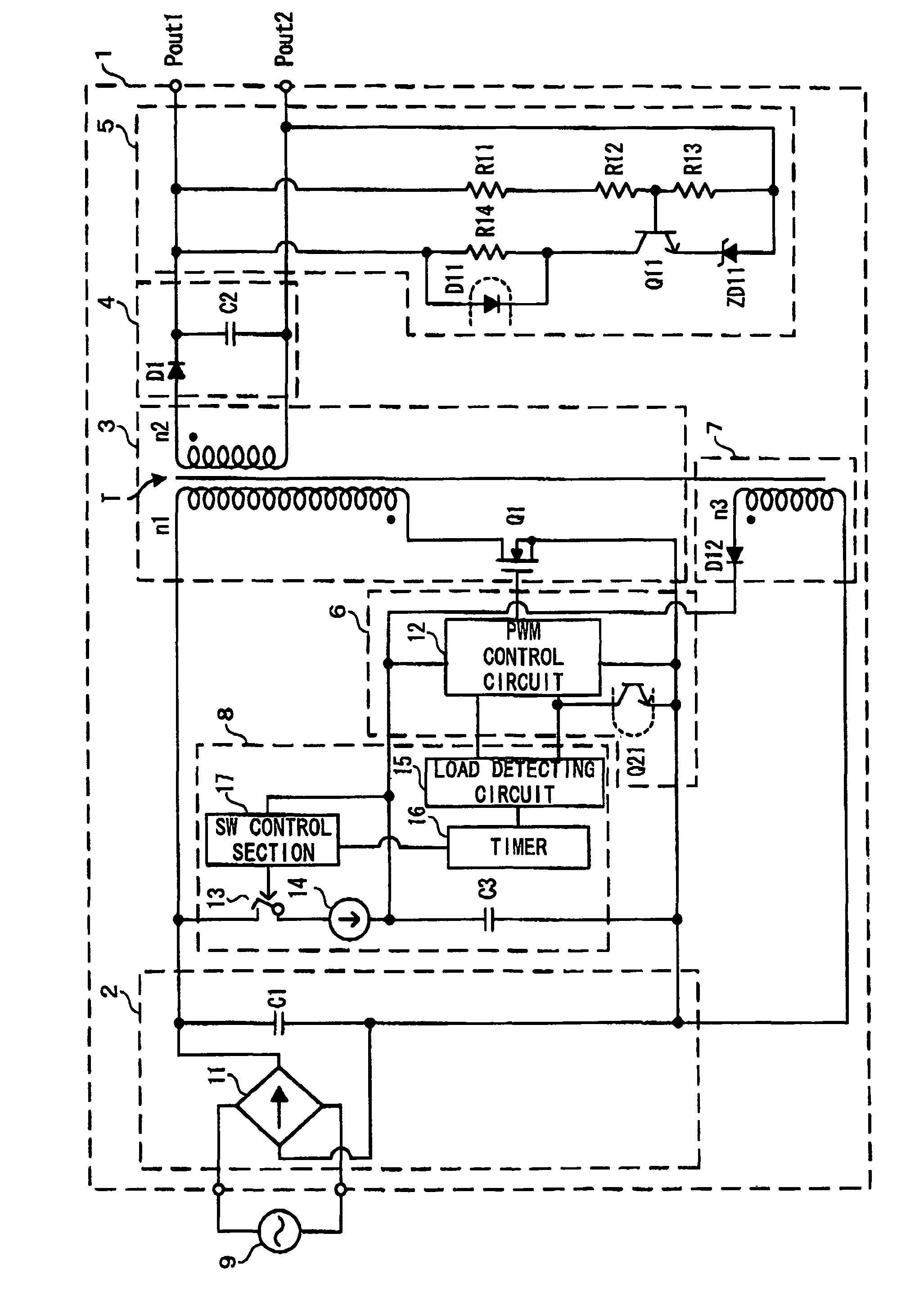
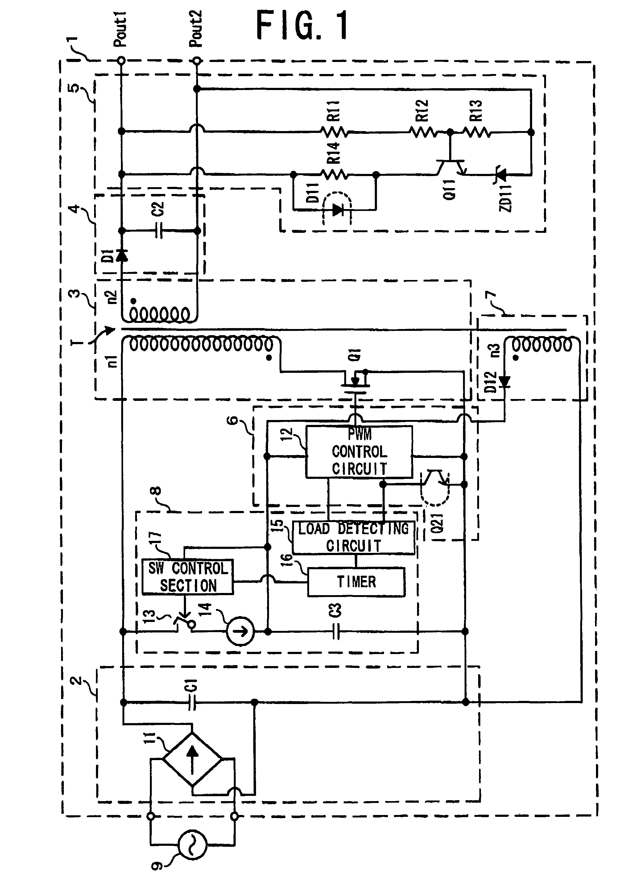
[0091]FIG. 1 shows the structure of a converter according to the first embodiment.
[0092]A converter 1 according to the first embodiment is constituted by a flyback converter, and comprises an AC-DC converting section 2, a voltage converting section 3, a rectifying and smoothing section 4, an output voltage detecting section 5, a control section 6, an auxiliary power supply section 7 and a drive-control voltage supply section 8.
[0093]The AC-DC converting section 2, the voltage converting section 3 and the rectifying and smoothing section 4 generate a voltage to be supplied to a load, and the AC-DC converting section 2 receives an AC voltage and applies a rectified and smoothed DC voltage to a primary winding n1 of the transformer T. AC power from an AC power supply 9 is converted to DC power. The AC-DC converting section 2 includes a rectifying circuit 11 and a capacitor C1.
[0094]The rectifying circuit 11 is constituted by a bridge rectifying circuit comprising four diodes (not shown...
second embodiment
[0145]A converter according to the second embodiment is designed to use a resistor as the constant current supply section.
[0146]FIG. 6 shows the structure of a converter 1 according to the second embodiment.
[0147]As shown in FIG. 6, the converter 1 according to the second embodiment comprises a resistor R21 as the constant current supply section of the drive-control voltage supply section 8. One end of the resistor R21 is connected to the other end of the switch 13, while the other end of the resistor R21 is connected to one end of the capacitor C3.
[0148]When the constant current supply section 14 supplies the constant current to the capacitor C3 as in the converter 1 according to the first embodiment the constant current is supplied to the capacitor C3 regardless of the voltage level of the DC voltage that is supplied from the AC-DC converting section 2. Accordingly, the charging time of the capacitor C3 becomes constant.
[0149]With the resistor R21 provided instead of the constant ...
third embodiment
[0150]A converter 1 according to the third embodiment is constructed by connecting a switch to a capacitor in parallel in the drive-control voltage supply section.
[0151]FIG. 7 shows the structure of a converter 1 according to the third embodiment.
[0152]The converter 1 according to the third embodiment, like the converter 1 according to the second embodiment, has a resistor R21 in the drive-control voltage supply section 8. It is to be noted however that one end of the resistor R21 is connected to one end of the capacitor C1 of the AC-DC converting section 2, and one end of the switch 13 is connected to one end of the capacitor C3 while the other end of the switch 13 is connected to the other end of the capacitor C3.
[0153]The operation of the converter 1 according to the third embodiment will be described.
[0154]In the converter 1 according to the third embodiment, the switch 13 is off when the AC power supply 9 is powered on.
[0155]When the AC power supply 9 is powered on, the capacit...
PUM
 Abstract
Description
Claims
Application Information
 - R&D
- Intellectual Property
- Life Sciences
- Materials
- Tech Scout
- Unparalleled Data Quality
- Higher Quality Content
- 60% Fewer Hallucinations
Browse by: Latest US Patents, China's latest patents, Technical Efficacy Thesaurus, Application Domain, Technology Topic, Popular Technical Reports.
© 2025 PatSnap. All rights reserved.Legal|Privacy policy|Modern Slavery Act Transparency Statement|Sitemap|About US| Contact US: help@patsnap.com