Venturi flow sensor

a flow sensor and flow sensor technology, applied in the field of flow sensors, can solve the problems of high cost of devices, many hospitals and medical facilities cannot afford or do not have access to such expensive machines

Active Publication Date: 2010-06-08
HONEYWELL INT INC
View PDF12 Cites 19 Cited by
  • Summary
  • Abstract
  • Description
  • Claims
  • Application Information

AI Technical Summary

Benefits of technology

[0007]It is another aspect of the present invention to provide an improved method and system for sensing flow without causing a significant global pressure change.
[0008]It is yet another aspect of the present invention to provide an improved method and system for sensing flow in mechanical breathing machines without inducing a pressure change which may be uncomfortable to the patient and detrimental to the operation of the machine.

Problems solved by technology

Such pressure changes, however, are often uncomfortable for the patient and do not promote optimal fan performance.
These types of devices, however, are often expensive.
Many hospitals and medical facilities cannot afford or do not have access to such expensive machines.

Method used


Image

  • Venturi flow sensor
  • Venturi flow sensor
  • Venturi flow sensor

Examples


Embodiment Construction

[0018]The particular values and configurations discussed in these non-limiting examples can be varied and are cited merely to illustrate at least one embodiment of the present invention and are not intended to limit the scope of the invention.

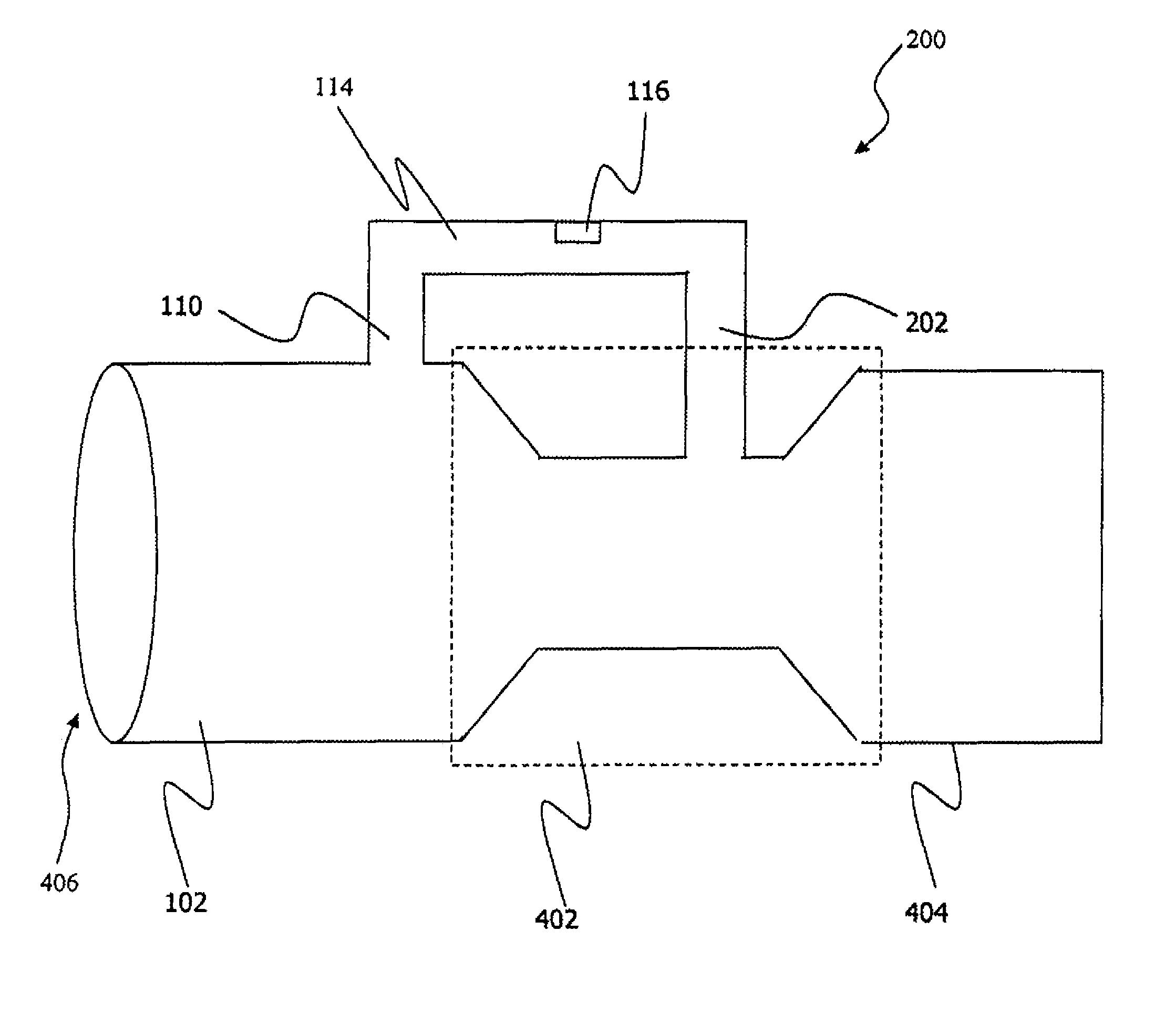
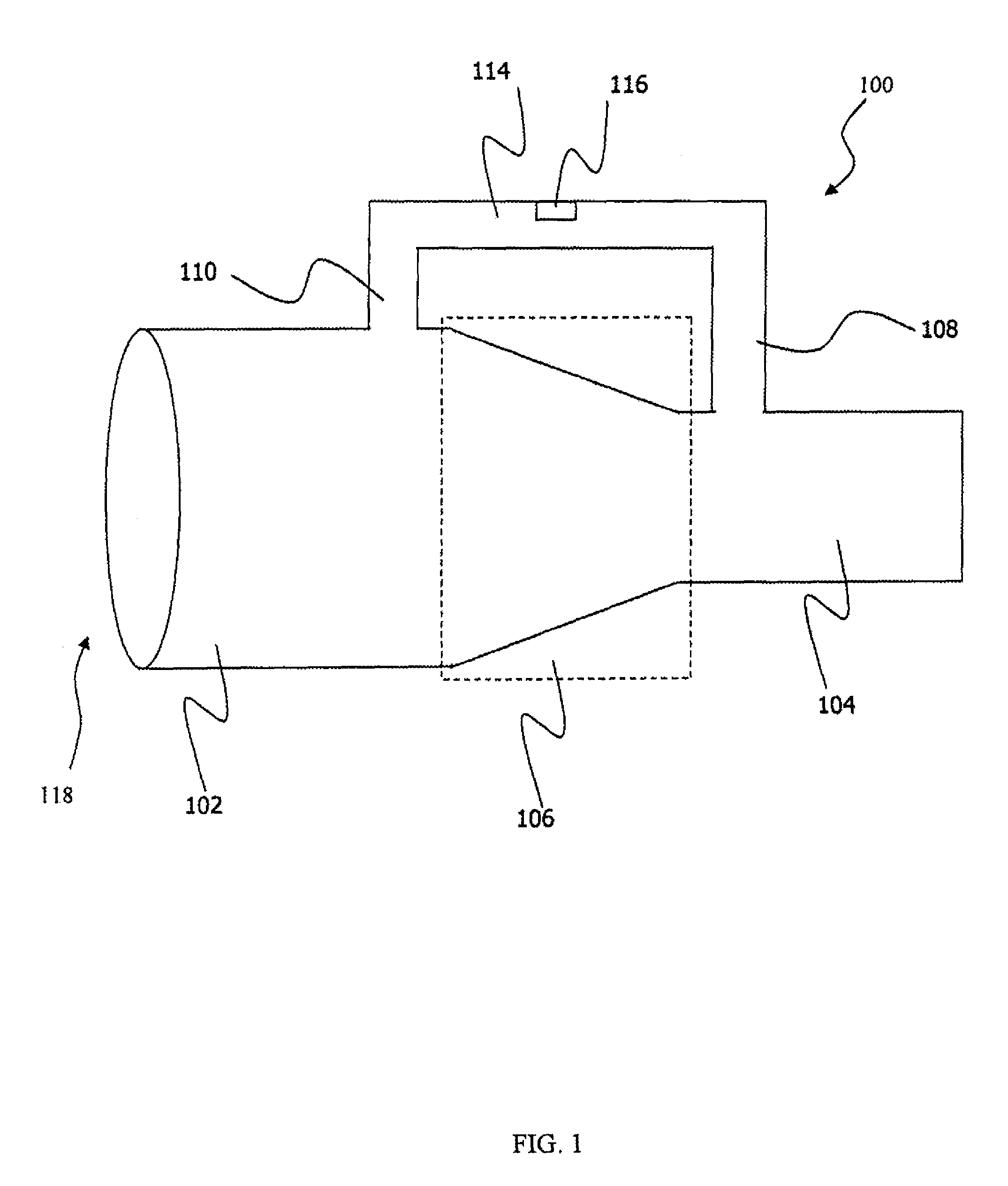
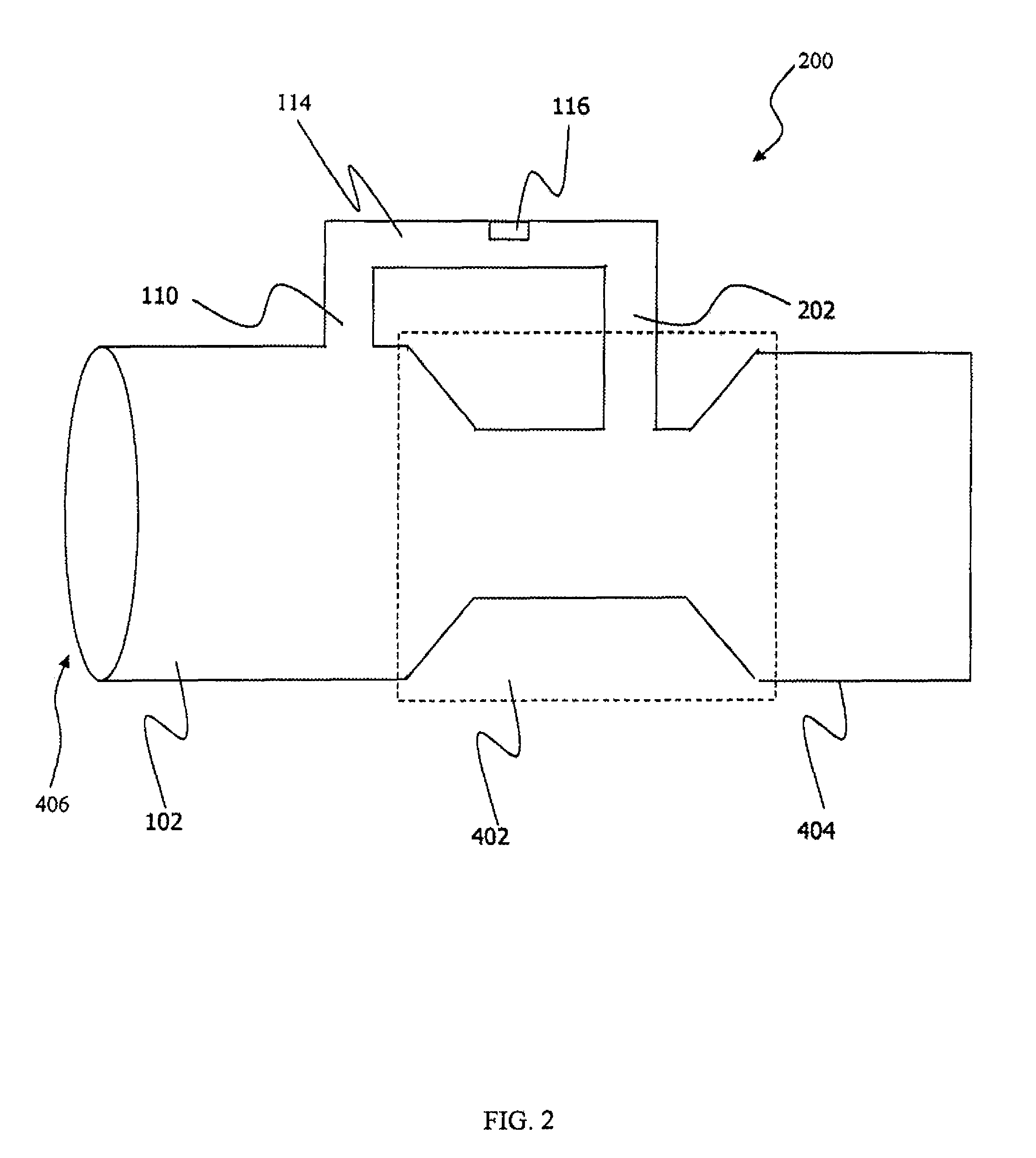
[0019]FIG. 1 illustrates a side view of one embodiment of a venturi flow sensor 100, which can be implemented in accordance with a preferred embodiment. Venturi flow sensor 100 consists of a cylindrically enclosed flow chamber 118 and a bypass flow chamber 114 connected to the cylindrically enclosed flow chamber 118 via taps 108 and 110. Cylindrically enclosed flow chamber 118 may be composed of three separate segments. Flow chamber 118's first segment 102 has a larger diameter than the last segment 104. In between segment 102 and 104 is a tapered venturi region 106 which tapers from the larger diameter of segment 102 to the smaller diameter of segment 106. This segment causes a venturi effect in cylindrically enclosed flow chamber 118 when a f...


PUM


Abstract

A venturi flow sensing method, system, and apparatus. A tube or chamber may be tapered from a larger to smaller diameter to create a venturi region within the tube or chamber. The venturi region causes a local increase in flow velocity. The change in velocity creates a local change in pressure which is, in turn, used to drive flow through a parallel bypass tube or chamber. Inside this bypass, a flow sensor can be located, and in some cases, a pressure sensor as well. The flow is then either exhausted back into the original tube or the bypass tube may alternatively dead end. In either case, flow can be measured without causing a significant overall pressure drop in the system.

Description

TECHNICAL FIELD[0001]Embodiments are generally related to flow sensors. Embodiments are also related to the measurement of airflow and pressure. Embodiments additionally relate to the flow sensors utilized in medical applications.BACKGROUND OF THE INVENTION[0002]Medical devices such as ventilators and CPAP (Continuous Positive Airway Pressure) machines are designed to provide air to a patient to foster correct breathing. A ventilator, for example, is designed to move air in and out of a person's lungs to assist breathing mechanically (e.g., a life support machine). A similar device is a respirator, which is used to assist or control breathing. Other similar machines facilitate breathing in persons with an impaired diaphragm function. These and other mechanical breathing devices often require a significant pressure change in order to accurately measure airflow. Such pressure changes, however, are often uncomfortable for the patient and do not promote optimal fan performance.[0003]Flo...

Claims


Application Information

Patent Timeline
Patent Type & Authority Patents(United States)
IPC IPC(8): G01F1/44
CPCG01F1/363G01F1/44G01F5/00G01F1/6845G01F1/6842
Inventor SPELDRICH, JAMIE W.
Owner HONEYWELL INT INC
Why Eureka
Try Eureka