
Fabric spreader with a lightweight hollow metal spreader rod for a loom

a technology of hollow metal and fabric spreader rod, which is applied in the field of fabric spreader with a lightweight hollow metal spreader rod for a loom, can solve the problems of high degree and rate of wear, relatively heavy weight of coated solid metal spreader rod, and unsatisfactory operation and handling

Inactive Publication Date: 2003-09-18
LINDAUER DORNIER GMBH
View PDF5 Cites 5 Cited by
  • Summary
  • Abstract
  • Description
  • Claims
  • Application Information

AI Technical Summary

Benefits of technology

[0008] More particularly and preferably according to the invention, the hollow cylindrical metal spreader rod consists entirely of V4A stainless steel, has an outer diameter of at least 10 mm with a wall thickness of at least 0.4 mm, preferably a wall thickness of 0.7 mm for an outer diameter of 15 mm. Further preferably, the wall thickness does not exceed 6% or especially does not exceed 5% of the outer diameter of the spreader rod. For example, the wall thickness can be limited to not more than 1.2 mm in typical embodiments. Thereby, the hollow spreader rod is quite thin-walled, is very lightweight, and has a low moment of inertia with respect to its free rotation, yet is still sufficiently strong and stiff over the weaving width to carry out its intended function and operation. Making the wall thickness greater would unnecessarily increase the cost, weight and rotational inertia, while detracting from the best operability of the spreader rod.
[0009] The outer circumferential surface of the metal spreader rod, which comes directly into contact with the woven fabric, has a surface roughness characteristic with a peak-to-valley height of at least 10 .mu.m, preferably a surface roughness of from 20 to 50 .mu.m. This surface roughness provides good engagement between the woven fabric and the spreader rod, so that the spreader rod exerts a good spreading effect, without requiring needles, pins, or the like which would penetrate the fabric. Instead, there is merely a surface frictional contact engagement between the fabric and the spreader rod. It has been found that a surface roughness below 10 .mu.m does not provide a sufficient frictional engagement with the fabric, while a surface roughness greater than 50 .mu.m does not provide any operational benefit, is more difficult to provide, and can even provide worse operating characteristics. The specified micro-roughened finish can be provided on the spreader rod by subjecting the circumferential surface thereof to any suitable known metal surface treatment, such as mechanical embossing, mechanical grinding, grit blasting, chemical etching, electro-spark or plasma treatments, etc.

Problems solved by technology

Such rubber-coated solid metal spreader rods are relatively heavy and have thus been found unsatisfactory in their operation and in their handling in connection with the operation and equipping of a modern high speed loom.
In practice, both the rubber-coated metal spreader rods as well as the solid polymer spreader rods suffer the disadvantage of a relatively high degree and rate of wear, which leads to a relatively short operating life.
In order to maintain satisfactory operation, it thus becomes necessary to frequently replace the spreader rod, which leads to increased loom operating costs.
Making the wall thickness greater would unnecessarily increase the cost, weight and rotational inertia, while detracting from the best operability of the spreader rod.
It has been found that a surface roughness below 10 .mu.m does not provide a sufficient frictional engagement with the fabric, while a surface roughness greater than 50 .mu.m does not provide any operational benefit, is more difficult to provide, and can even provide worse operating characteristics.

Method used


Image

  • Fabric spreader with a lightweight hollow metal spreader rod for a loom
  • Fabric spreader with a lightweight hollow metal spreader rod for a loom

Examples


Embodiment Construction

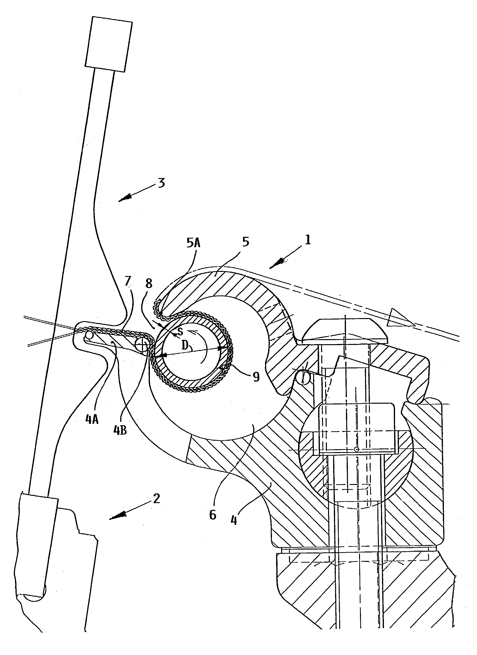
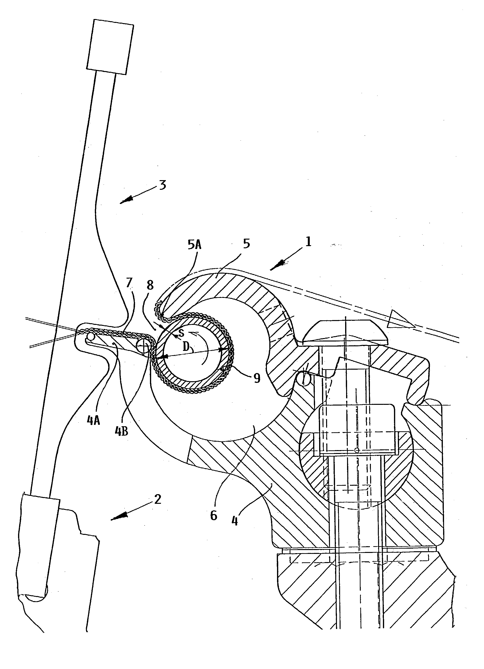
[0011] The present example embodiment of a fabric spreader arrangement 1 or spreader table 1 according to the invention is to be arranged in a generally conventional manner in a loom, such as an air jet loom. The single drawing FIGURE schematically shows a partially sectioned side view of the inventive fabric spreader arrangement 1 arranged in connection with the weaving reed 3 carried by a reed support 2, e.g. reed batten or sley 2 in an air jet loom.

[0012] The fabric spreader arrangement 1 comprises a fabric spreader body structure that includes a fabric spreader body 4 and a cover 5, as well as a spreader rod 9. The spreader body 4 is releasably or removably connected to the machine frame of the loom, for example by bolts as schematically shown. The spreader body 4 has a length that extends along the maximum weaving width of the loom. The removable cover 5 is removably secured relative to the spreader body 4, for example also by bolts or the like. The removable cover 5 and the sp...


PUM

PropertyMeasurementUnit
surface roughnessaaaaaaaaaa
thicknessaaaaaaaaaa
outer diameteraaaaaaaaaa

Abstract

A fabric spreader arrangement for a loom includes a spreader rod rotatably received in a hollow space of a spreader body. The fabric is looped around the spreader rod in the hollow space. To achieve a low wear, a light weight, and an excellent fabric spreading effect, the spreader rod is a one-piece hollow cylindrical metal body extending entirely over the weaving width, preferably made of V4A stainless steel, having an outer diameter of at least 10 mm (and preferably 15 mm) with a wall thickness of at least 0.4 mm (and preferably 0.7 mm), and having an outer circumferential surface that has been surface treated to achieve a surface roughness with a peak-to-valley roughness measurement of at least 10 mum (and preferably 20 to 50 mum).

Description

PRIORITY CLAIM[0001] This application is based on and claims the priority under 35 U.S.C. .sctn.119 of German Patent Application 102 11 149.9, filed on Mar. 14, 2003, the entire disclosure of which is incorporated herein by reference.[0002] The invention relates to a spreader arrangement for spreading, in the weaving width direction, the woven fabric being produced on a loom.BACKGROUND INFORMATION[0003] It is generally known in the art to provide a spreader arrangement in a loom, downstream of the beat-up and interlacing point, for spreading the width of the woven fabric that is being produced, so as to prevent the fabric from contracting in the widthwise direction. Various configurations of such spreader arrangements are known. For example, it is known to provide a fabric spreader body that substantially encloses a hollow space therein, and that has two fabric deflection elements with an open fabric slot therebetween, which communicates into the hollow space. The fabric spreader bo...

Claims


Application Information

Patent Timeline
Patent Type & Authority Applications(United States)
IPC IPC(8): D03J1/22D06C3/06
CPCD03J1/223
Inventor KRUMM, VALENTIN
Owner LINDAUER DORNIER GMBH
Learn More