Electro-optic displays, and color filters for use therein

a technology applied in the field of optical displays and color filters, can solve the problems of inadequate service life of optical displays, preventing their widespread use, and gas-based electrophoretic media being susceptible to the same types of problems, so as to increase the thickness of the sub-assembly and prevent mechanical damage

Active Publication Date: 2012-01-17
E INK CORPORATION
View PDF300 Cites 191 Cited by
  • Summary
  • Abstract
  • Description
  • Claims
  • Application Information

AI Technical Summary

Benefits of technology

[0046]In this process, typically an adhesive layer will be provided between the electro-optic layer and the backplane. However, provided sufficient adhesion of the electro-optic layer to the backplane can be achieved, it is not always necessary to provide such a discrete electro-optic layer; for example, it is known from U.S. Pat. No. 7,110,164 that in some cases a polymeric binder component within an electro-optic layer can serve as an adhesive, thus eliminating the need for a discrete adhesive layer.
[0049]Also, in the process of the present invention, the electro-optic sub-assembly may further comprise a front substrate disposed on the opposed side of the electrically-conductive layer from the electro-optic layer, the front substrate providing mechanical support and protection to the electrically-conductive layer. In some cases the presence of such a front substrate is necessary because the electrically-conductive layer is not self-supporting; for example, when the electrically-conductive layer is formed of sputtered ITO, the ITO is typically of the order of 1 μm thick and is not self-supporting. This front substrate may have a thickness not greater than about 50 μm, and desirably not greater than about 25 μm; the front substrate remains in the final display and if it is too thick, it may give rise to parallax problems between the color filter array of the electro-optic layer. Whether or not a front substrate is present, the electro-optic sub-assembly may comprise a masking film; such a masking film can serve to substantially increase the thickness of the sub-assembly, thus facilitating handling of the sub-assembly, and may also serve to prevent mechanical damage to the electrically-conductive layer and / or front substrate (if present). The masking film is removed before lamination of the color filter array. The masking film may have a thickness of about 100-200 μm, although thicker films can be used if desired, for example to protect integrated circuits present on the backplane.

Problems solved by technology

Nevertheless, problems with the long-term image quality of these displays have prevented their widespread usage.
For example, particles that make up electrophoretic displays tend to settle, resulting in inadequate service-life for these displays.
Such gas-based electrophoretic media appear to be susceptible to the same types of problems due to particle settling as liquid-based electrophoretic media, when the media are used in an orientation which permits such settling, for example in a sign where the medium is disposed in a vertical plane.
Indeed, particle settling appears to be a more serious problem in gas-based electrophoretic media than in liquid-based ones, since the lower viscosity of gaseous suspending fluids as compared with liquid ones allows more rapid settling of the electrophoretic particles.
However, the methods used for assembling LCD's cannot be used with solid electro-optic displays.
This LCD assembly process cannot readily be transferred to solid electro-optic displays.
However, attaching a color filter to an electro-optic display in the correction position is a difficult operation.
Many color filter arrays are formed on sheets of glass or similar rigid material in order that the color filter will maintain stable dimensions (even slight distortions of the dimensions of a color filter array can lead to at least part of the color filter array being misaligned with the pixels of the display, with consequent errors in the colors displayed to an observer).
The lamination adhesive is tacky at room temperature , which makes is extremely difficult to laminate the two rigid sheets together without trapping pockets of air between them, especially if the sheets are of substantial size.
Despite the use of special alignment tools to keep the rigid sheet flat, and application of substantial pressure, of the order of 100 psig (about 0.8 MPa) at room temperature, it has been found that in practice it is difficult to avoid trapping significant numbers of air bubbles.
Such expedients for bubble removal substantially increase the cost and duration of the display assembly process, rendering it very time and labor intensive, and do not consistently result in high quality color displays.
Furthermore, it appears that this process for lamination of rigid, typically glass, sheets will not allow for a good manufacturing process, because it imposes a large additional set of electrical and Theological constraints that make the lamination very difficult.

Method used


Image

  • Electro-optic displays, and color filters for use therein
  • Electro-optic displays, and color filters for use therein
  • Electro-optic displays, and color filters for use therein

Examples


Embodiment Construction

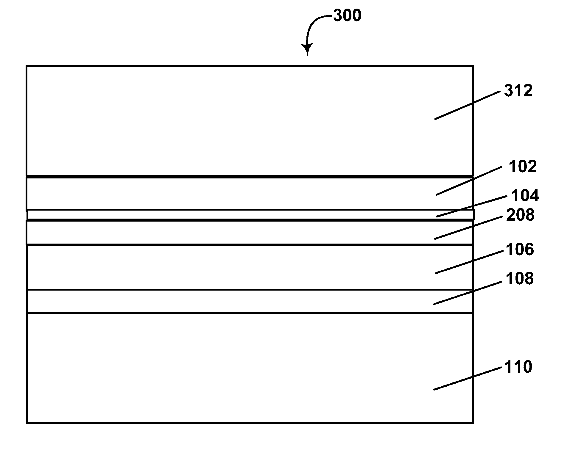
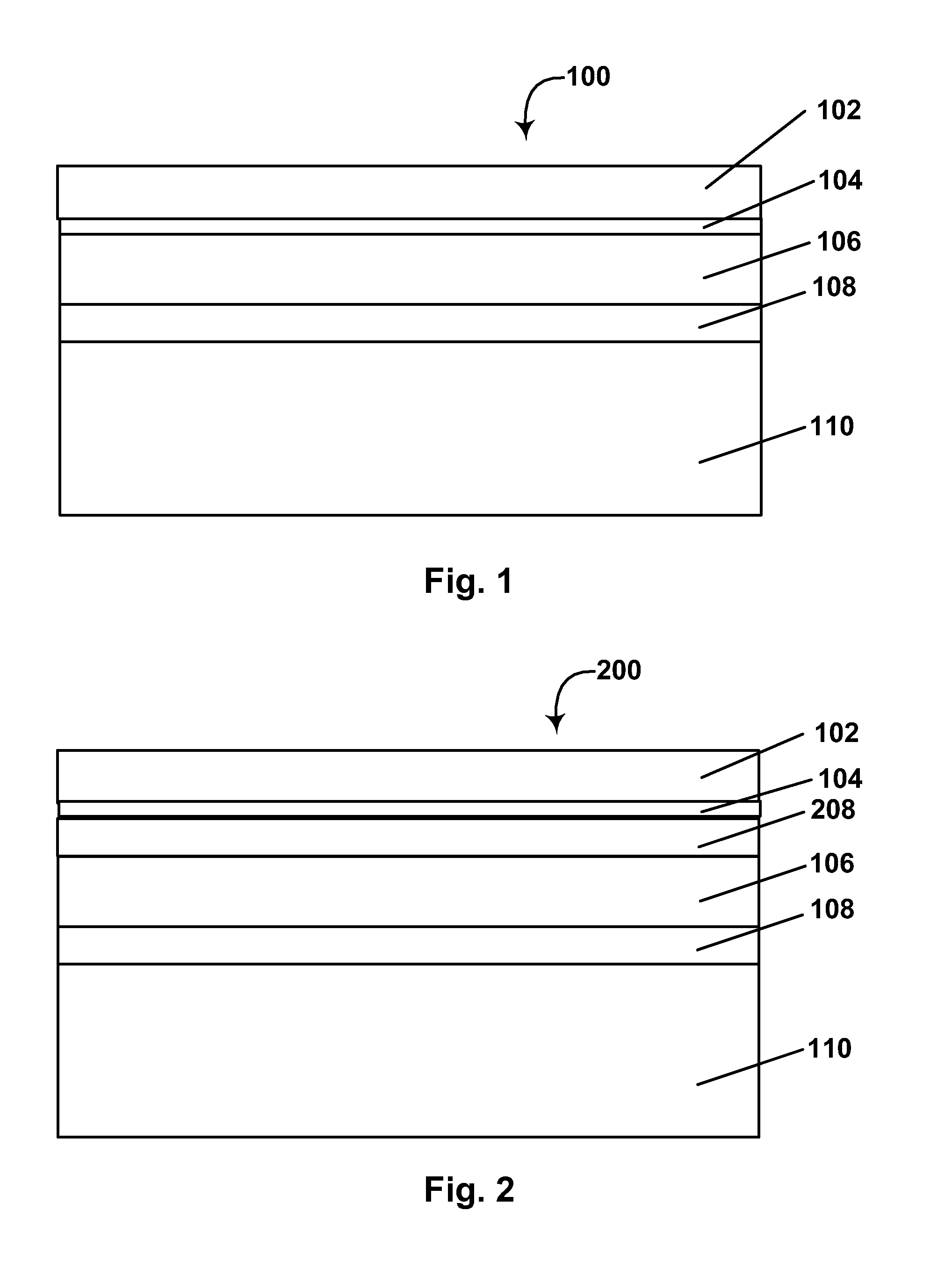
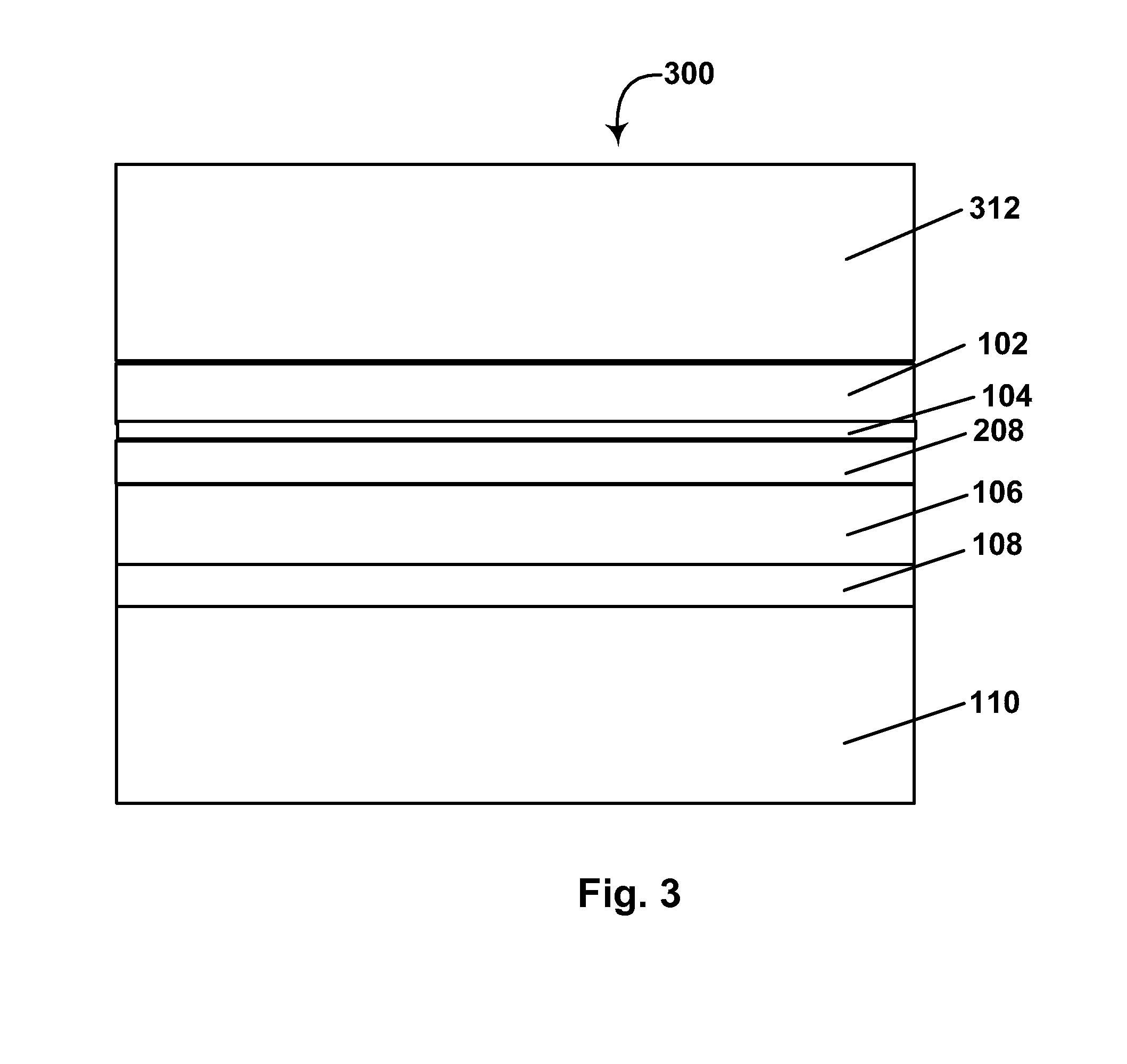
[0067]As already mentioned, the present invention provides a process for forming an electro-optic display in which a electro-optic layer and an electrically-conductive layer (typically in the form of a front plane laminate) are first laminated to a backplane. Thereafter, a flowable material is deposited over the electrically-conductive layer, and a color filter array (CFA) is placed over the electrically-conductive, these two steps being performed in either order. In some forms of the present process, the flowable material is cured after the CFA is in place; in others, a non-curable material is employed so that the material remains unchanged in the final display.

[0068]In the present process, the electro-optic layer is desirably provided in the form of a front plant laminate. This FPL may be a “classic” FPL as described in U.S. Pat. No. 6,982,178 or an inverted FPL as described in U.S. Patent Application Publication No. 2007 / 0109219. In either case, it is desirable to make the substr...


PUM

PropertyMeasurementUnit
diameteraaaaaaaaaa
thicknessaaaaaaaaaa
thicknessaaaaaaaaaa

Abstract

A process for producing a color electro-optic display uses an electro-optic sub-assembly comprising an electro-optic layer and a light-transmissive electrically-conductive layer. This sub-assembly is laminated to a backplane comprising a plurality of electrodes with the electro-optic layer disposed between the backplane and the electrically-conductive layer. A flowable material is placed over the sub-assembly and a color filter array is placed over the electrically-conductive layer and aligned with the electrodes of the backplane to form the color electro-optic display.

Description

REFERENCE TO RELATED APPLICATIONS[0001]This application is related to:[0002](a) Application Serial No. 10 / 817,464, filed Apr. 2, 2004 (Publication No. 2004 / 0190114, now U.S. Patent No. 7,667,684), which is a continuation of abandoned Application Serial No. 09 / 349,806, filed Jul. 8, 1999 and claiming benefit of Application Serial No. 60 / 092,050, filed Jul. 8, 1998;[0003](b) U.S. Patent No. 6,864,875; and[0004](c) U.S. Patent No. 7,075,502.[0005]The entire contents of this copending application and these patents, and of all other U.S. patents and published and copending applications mentioned below, are herein incorporated by reference.BACKGROUND OF INVENTION[0006]This invention relates to electro-optic displays and color filters for use in such displays.[0007]The term “electro-optic”, as applied to a material or a display, is used herein in its conventional meaning in the imaging art to refer to a material having first and second display states differing in at least one optical prope...

Claims


Application Information

Patent Timeline
Patent Type & Authority Patents(United States)
IPC IPC(8): G02B26/00G03G13/00G09G3/19G02F1/167G02F1/16755G02F1/1677G02F1/1679
CPCG02F1/167B32B37/1018B32B2037/268Y10T156/10B32B2457/20B32B2309/105G02F1/1677G02F1/1679G02F1/16755G02F2203/055
Inventor PAOLINI, JR., RICHARD J.BATTISTA, STEVEN JOSEPHALBERT, JONATHAN D.
Owner E INK CORPORATION
Why Eureka
Try Eureka