Radiator for light emitting unit, and backlight device

Inactive Publication Date: 2007-01-25
SONY CORP
View PDF4 Cites 194 Cited by
  • Summary
  • Abstract
  • Description
  • Claims
  • Application Information

AI Technical Summary

Benefits of technology

[0017] According to the radiator for a light emitting unit according to one embodiment of the present invention configured as above, the large quantity of heat generated as a result of the light operations of a multiplicity of light emitting diodes is efficiently conducted by the radiating plate and the heat pipe to the radiating section provided at a separate location. Therefore, according to the radiator for a light emitting unit, a light emitting unit which has a multiplicity of light emitting diodes as a light source and which emit light at high luminance through a stable operation can be obtained, without providing a radiating section directly at the light emitting portion. In addition, according to the radiator for a light emitting unit, the heat pipe is mounted in the heat pipe fitting recessed portion formed in the radiating plate in the state of making close contact with the heat pipe fitting recessed portion, so that it is possible to contrive an enhancement of the efficiency of the cooling function and to contrive a reduction in the thickness of the light emitting unit.
[0018] Besides, in the backlight device according to another embodiment of the present invention, a high capacity of display light is supplied to the transmission type display p

Problems solved by technology

Meanwhile, in the LED backlight device, a multiplicity of LEDs is provided and a large quantity of heat is generated from the LEDs.
In addition, the LED backlight device includes the diffusion plate and the reflective film as above-mentioned, and generation of deformation, denaturing or the like in these optical films due to the elevated temperature leads to degradation of the display accuracy.
However, the configuration in which the cooling airflow is blown directly to the diffusion film and the reflective film cannot be adopted, since this approach leads to the generation of vibrations or unintentional movements.
In the LED backlight device, there are the restrictive conditions that the thermally conductive member should not be disposed directly in the closed space portion because the

Method used


Image

  • Radiator for light emitting unit, and backlight device
  • Radiator for light emitting unit, and backlight device
  • Radiator for light emitting unit, and backlight device

Examples


Embodiment Construction

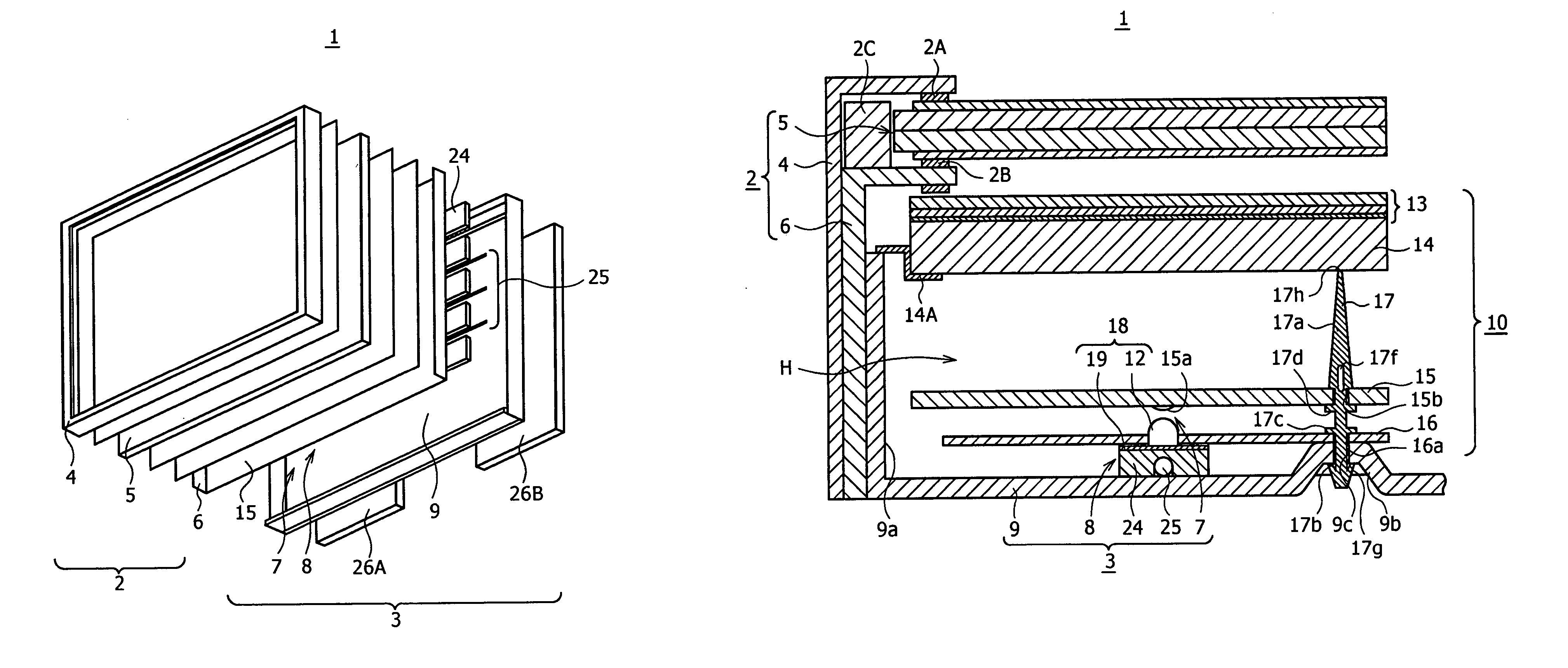
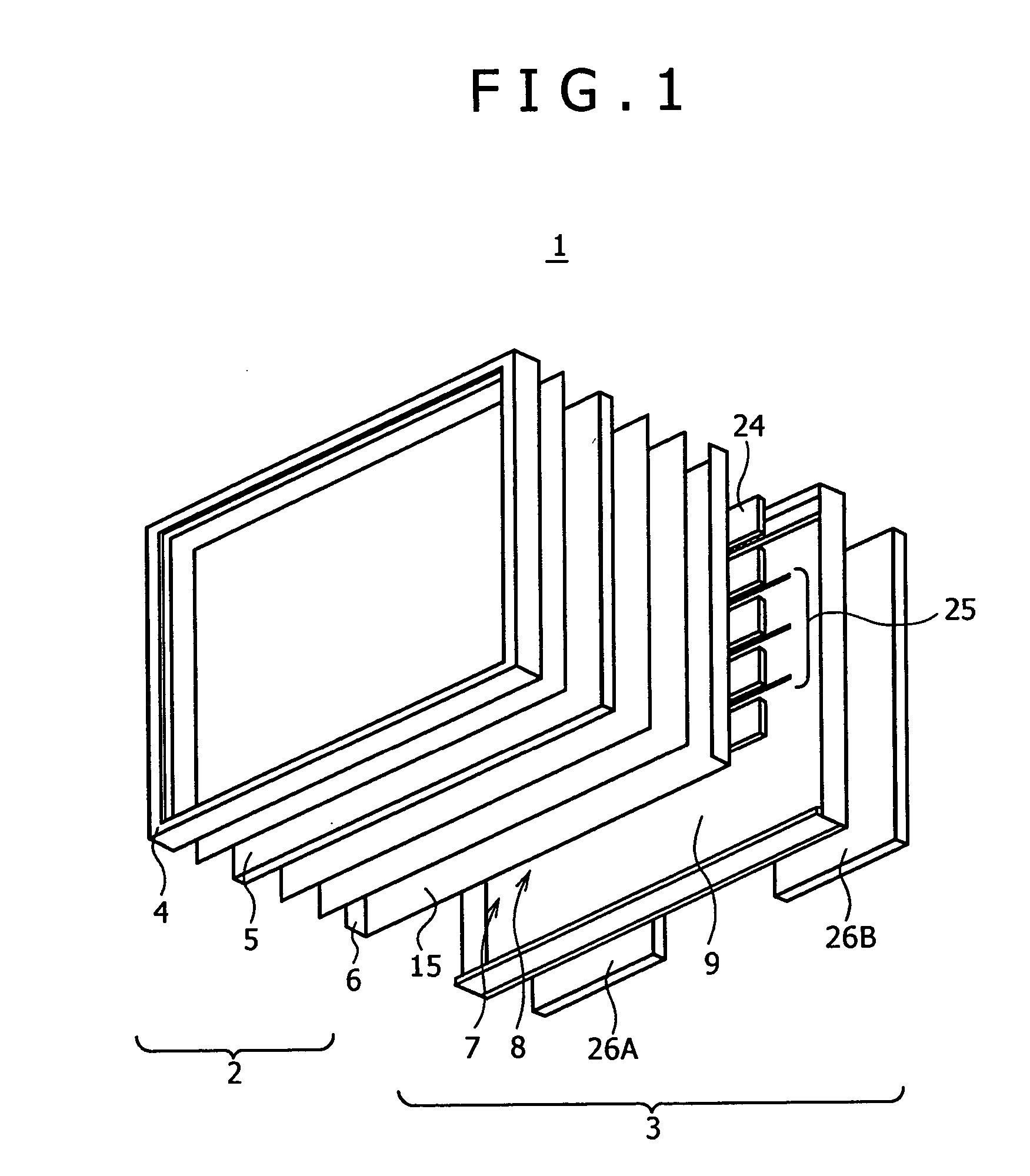
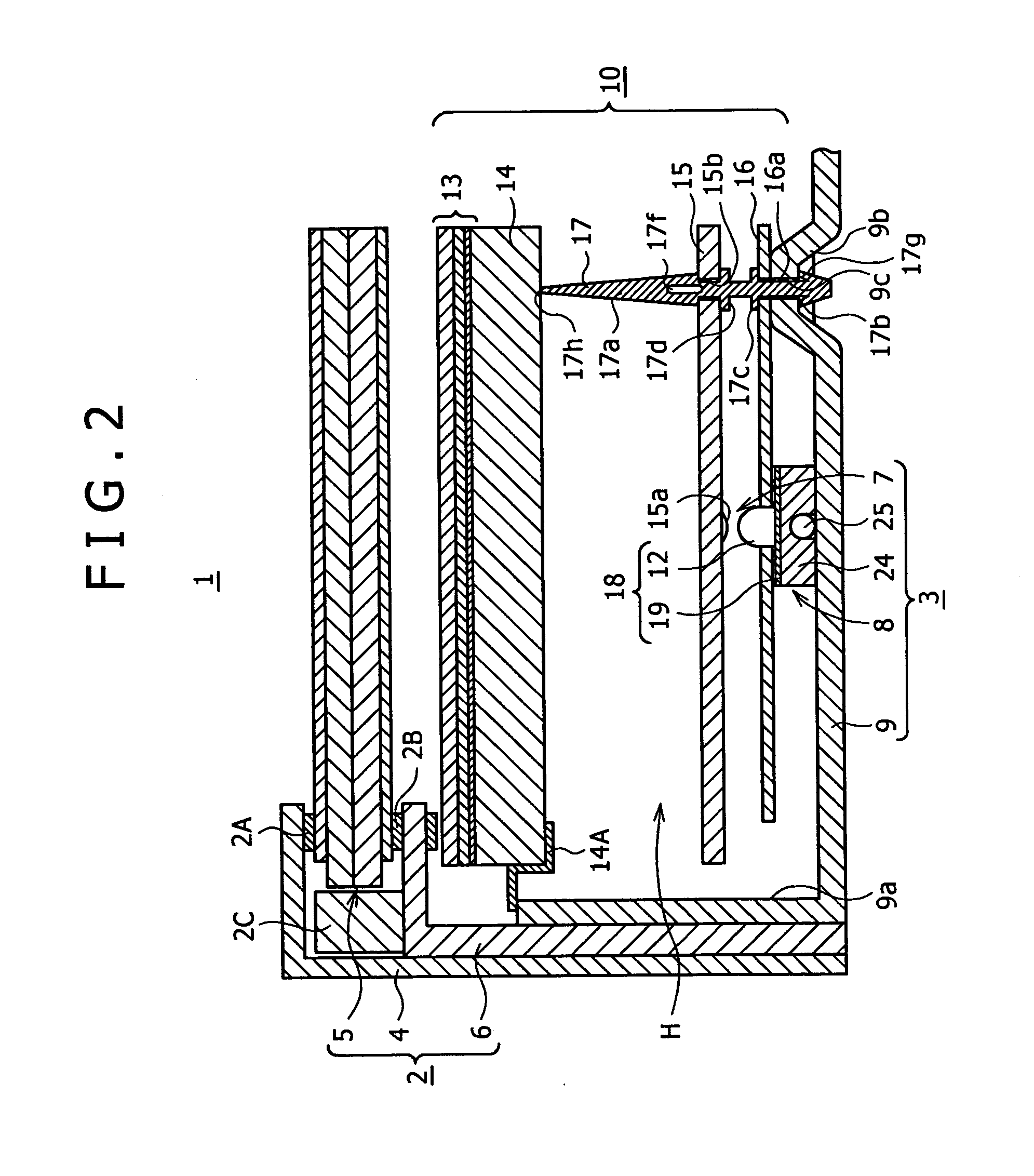
[0033] Now, a transmission type liquid crystal display panel 1 shown in the figures as an embodiment of the present invention will be described in detail below. The transmission type liquid crystal display panel 1 is used as a display panel of a TV set having a large display screen of 40 inches or more, for example. As shown in FIGS. 1 and 2, the transmission type liquid crystal display panel 1 includes a liquid crystal panel unit 2, and a backlight unit 3 combined with the back side of the liquid crystal panel unit 2 for supplying display light to the latter. The liquid crystal panel unit 2 includes a frame-like front frame member 4, a liquid crystal panel 5, and a frame-like back frame member 6 for clamping an outer peripheral portion of the liquid crystal panel 5 between itself and the front frame member 4 through spacers 2A, 2B, a guide member 2C and the like.

[0034] Though details are omitted, the liquid crystal panel 5 has a structure in which a liquid crystal is sealed betwee...


PUM


Abstract

The present invention provides a radiator for a light emitting unit, annexed to the light emitting unit including a multiplicity of light emitting diodes mounted on substantially the same axis line on a first principal surface of a wiring substrate. The radiator includes a radiating plate and a heat pipe. The radiating plate is combined with the wiring substrate, with a first principal surface faced as a faying surface to a second principal surface opposite to the first principal surface of the wiring substrate, and is provided with a heat pipe fitting portion. The heat pipe is mounted into the heat pipe fitting portion of the radiating plate while keeping close contact with the inner wall of the heat pipe fitting portion. The heat generated from the light emitting diode group is transferred to a radiating means through the radiating plate and the heat pipe.

Description

CROSS REFERENCES TO RELATED APPLICATIONS [0001] The present invention contains subject matter related to Japanese Patent Application JP 2004-136919 filed in the Japanese Patent Office on Apr. 30, 2004, the entire contents of which being incorporated herein by reference. BACKGROUND OF THE INVENTION [0002] The present invention relates to a backlight device provided, for example, in a transmission type liquid crystal display (LCD) or the like, and to a radiator annexed to the backlight device. [0003] The liquid crystal display is suitable for contriving a larger display screen, a lighter weight, a thinner shape, a lower power consumption and the like, as compared with the cathode ray tube (CRT). Therefore, liquid crystal displays have come to be used for TV sets and various displays, together with, for example, the self-light-emitting type PDPs (Plasma Display Panels) and the like. The liquid crystal display has a liquid crystal panel in which liquid crystals are sealed between two tr...

Claims


Application Information

Patent Timeline
IPC IPC(8): F21V29/00F21V29/505
CPCG02F2001/133628G02F1/133603G02F1/133628H05K7/2099
Inventor HAFUKA, TABITOSHIBATA, HIROKAZU
Owner SONY CORP
Why Eureka
Try Eureka