AI technical title is built by Patsnap AI team. It summarizes the technical point description of the patent document.
a technology for lifting chairs and chairs, applied in the field of chair lifts, can solve the problems of weakening the specific muscles used in this process, elderly adults and persons with disabilities have difficulty standing up from a seated position, and achieve the effect of great mechanical advantag
Inactive Publication Date: 2010-06-15
COMBS JOHN A
View PDF26 Cites 14 Cited by
Summary
Abstract
Description
Claims
Application Information
AI Technical Summary
This helps you quickly interpret patents by identifying the three key elements:
Problems solved by technology
Method used
Benefits of technology
Benefits of technology
"The present invention provides a lift chair that is designed for elderly individuals, people with disabilities, and those who struggle to stand up from a seated position. The chair has a frame with legs and a back rest portion, and it includes arm rests that can move from a first horizontal position to a second angled lift position. The chair is lightweight, affordable, and convenient. The technical effects of the invention include a comfortable and ergonomic design that reduces stress on the body, provides better circulation, and is easy to use."
Problems solved by technology
Many senior citizens, older adults and persons with disabilities have difficulty standing up from a seated position.
Unfortunately, the elderly struggle because the specific muscles used for this process tend to get weaker as they age.
This causes muscles to atrophy (decrease in size) over time if they are not used.
Because elderly persons have trouble lowering and raising their bodies into and out of chairs, many products are on the market but they tend to be expensive, heavy and bulky.
Method used
Image
Click on the blue label to locate the original text in one second.
Reading with bidirectional positioning of images and text.
Examples
Embodiment Construction
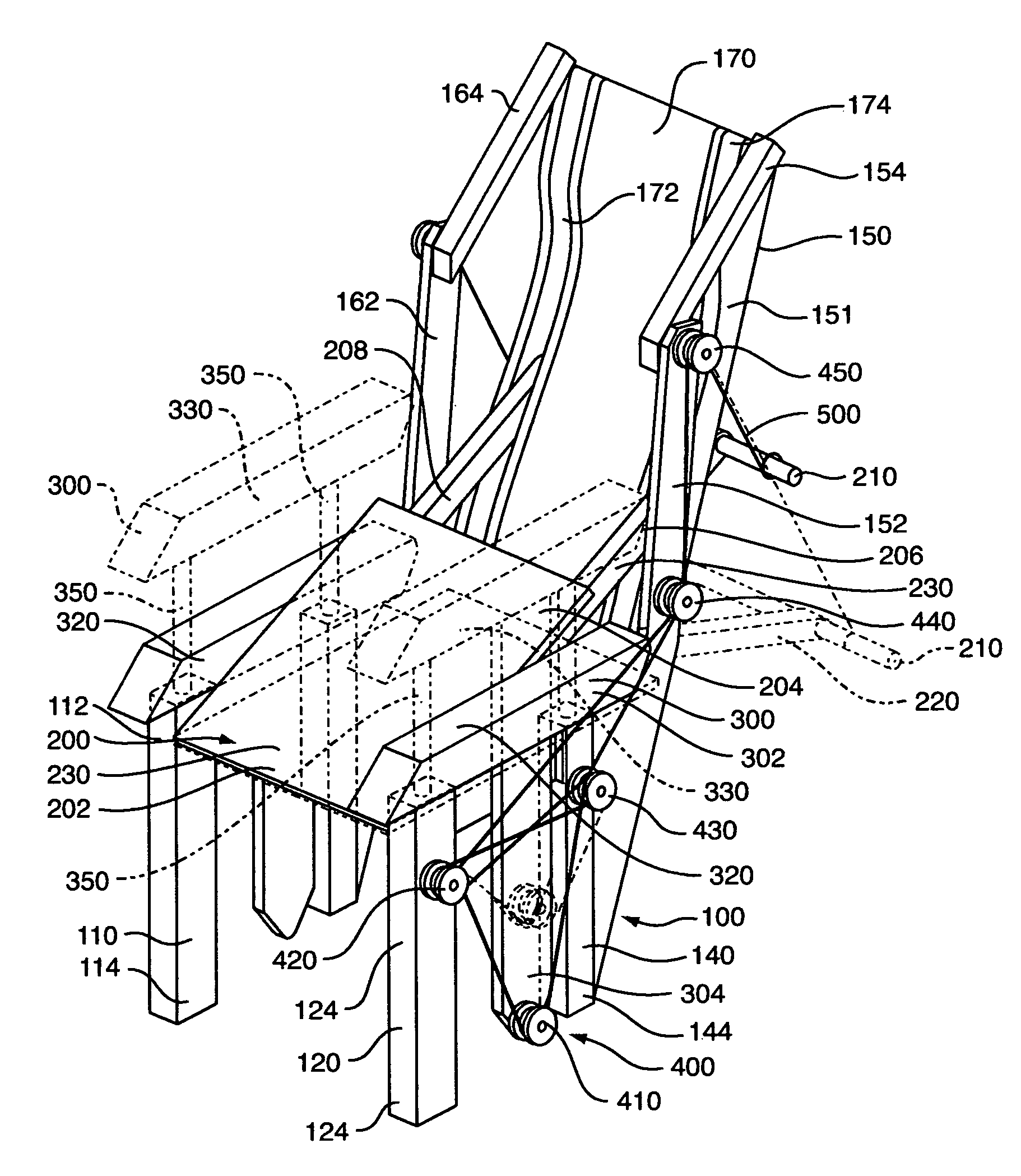
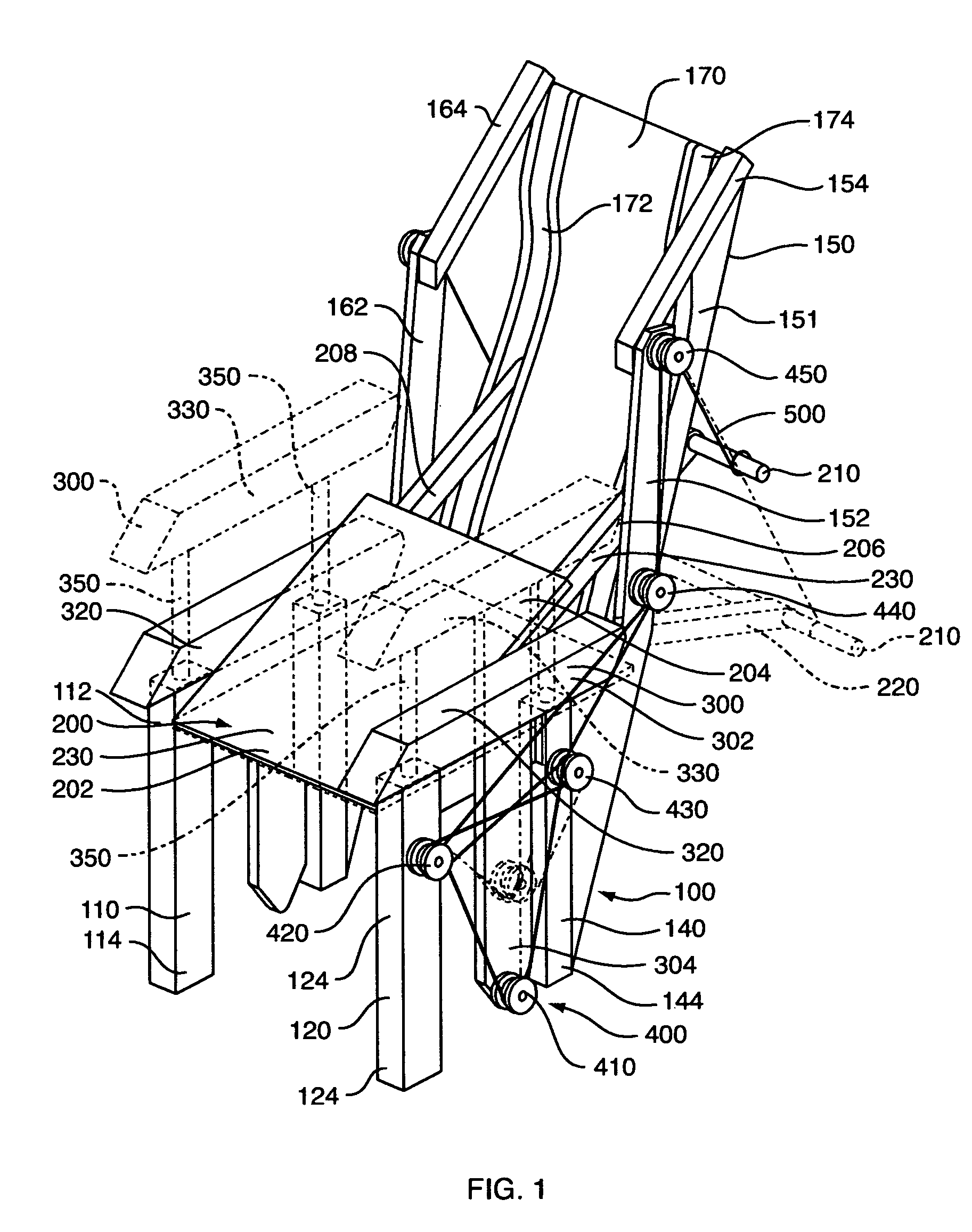
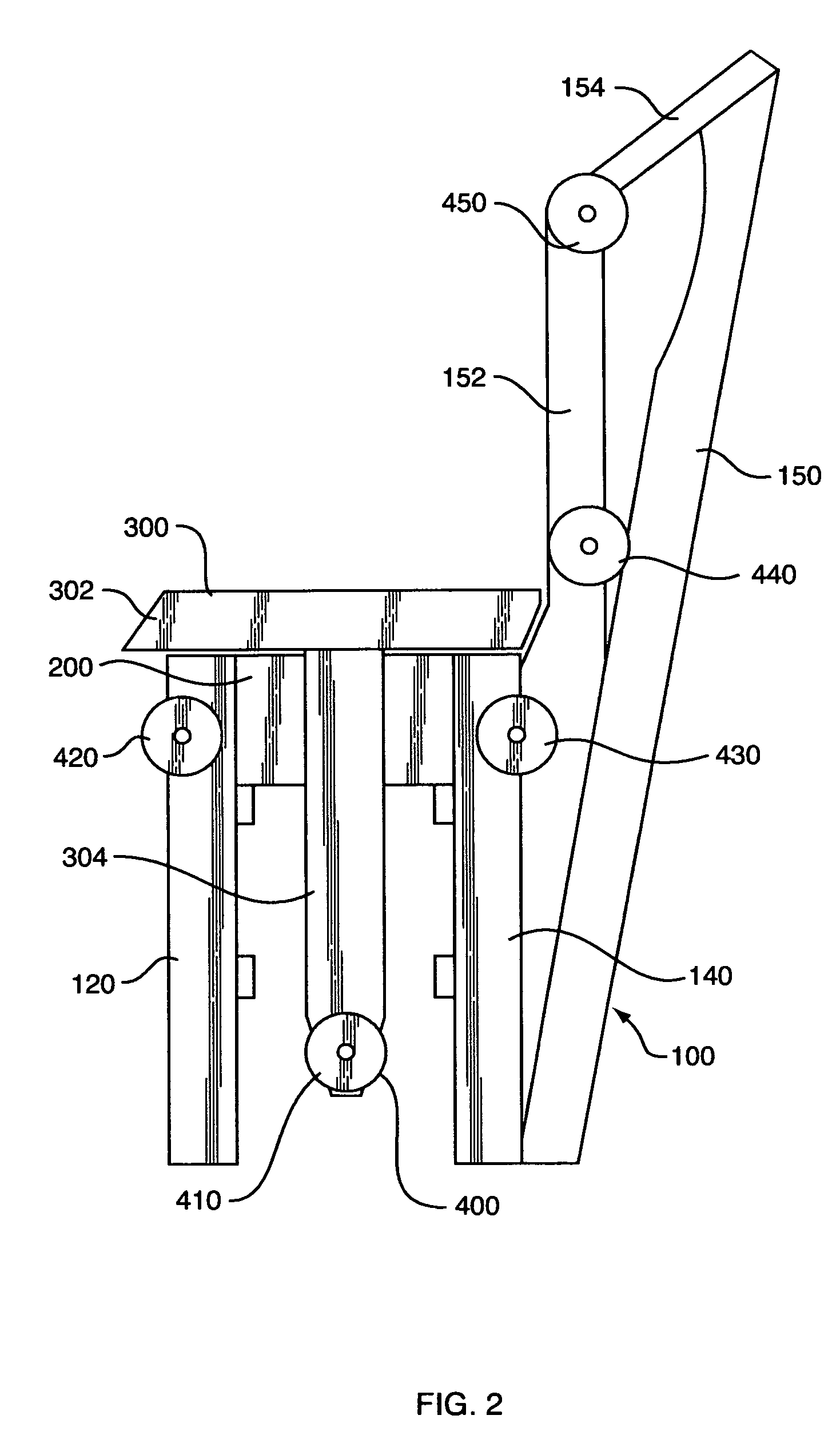
[0035]Referring to FIG. 1 the lift chair of the present invention has a frame 100 which includes legs 110, 120, 130 and 140 and a back rest portion 150. A seat 200 has a front portion 202 which is pivotally attached to said frame at 205 (FIG. 8) and has a rear portion 204. The seat 200 movable from a first generally horizontal sitting position 220 (FIG. 7) to a second angled lift position 230 (FIG. 8) wherein the rear portion 204 of said seat 200 is lifted upwardly. Arm rest members 300 are movably attached to opposite sides of said frame 100. Each arm rest member 300 has a generally horizontal arm rest portion 302 and a vertical activating rod member 304 attached to said arm rest portion 302. The arm rests 300 are movable from a first upper vertical position 330 (FIG. 7) to a second lower vertical position 320 (FIG. 8). A rope and pulley means 400 including a rod pulley 410 attached to a lower end of each activating rod 304 and plural pulleys including front pulley 420 attached to ...
PUM
Abstract
A lift chair is provided which includes a frame having four legs and a back rest portion. A seat has a front portion pivotally attached to the frame and has a rear portion which can be lifted upwardly. The seat movable from a first generally horizontal sitting position to a second angled lift position where the rear portion of said seat is lifted upwardly. Arm rests members are movably attached to opposite sides of the frame. Each arm rest member has a generally horizontal arm rest portion and a vertical activating rod member. The arm rests are movable from a first upper vertical position to a second lower vertical position. A rope and pulleysystem is provided which includes a pulley attached to a lower end of each activating rod and additional pulleys are attached to the frame. A rope is attached to the rear portion of the seat and extends around the pulleys. When a user pushes downwardly on the arm rests, the arm rests together with the rope and pulleys cause the rear portion of said seat to be lifted upwardly thus helping the user to stand up and get out of the chair.
Description
BACKGROUND OF THE INVENTION[0001]1. Field of the Intention[0002]The present invention relates to a chair lift. More specifically, the present invention relates to a chair which allows a user to push downwardly on arm rests to cause, with the help of ropes and pulleys, a rear portion of said seat to be efficiently lifted upwardly thus helping the user to stand up and get out of the chair.[0003]2. Description of the Prior Art[0004]A variety of lift chair devices have been proposed over the years. A number of existing patents teach the use of an electric screw drive or the like to lift all or a large portion of a chair to assist a user to stand up. Examples of such devices include: Ambrose, Jr. et al., U.S. Pat. No. 6,106,062; Lin, U.S. Pat. No. 5,312,153; Gaffney, U.S. Pat. No. 4,083,599; Mohn et al., U.S. Pat. No. 7,090,297; Gaffney, U.S. Pat. No. 4,909,569; Rudes et al., U.S. Pat. No. 5,294,179; and Kemmerer et al., U.S. Pat. No. 5,931,532.[0005]Marcoux et al., U.S. Pat. No. 6,213,5...
Claims
Application Information
Patent Timeline
Application Date:The date an application was filed.
Publication Date:The date a patent or application was officially published.
First Publication Date:The earliest publication date of a patent with the same application number.
Issue Date:Publication date of the patent grant document.
PCT Entry Date:The Entry date of PCT National Phase.
Estimated Expiry Date:The statutory expiry date of a patent right according to the Patent Law, and it is the longest term of protection that the patent right can achieve without the termination of the patent right due to other reasons(Term extension factor has been taken into account ).
Invalid Date:Actual expiry date is based on effective date or publication date of legal transaction data of invalid patent.

