Supercharge Your Innovation With Domain-Expert AI Agents!

Machine with support elements

a technology of supporting elements and machines, applied in the field of machines, can solve the problems of affecting the quality of production, and affecting the production rate, so as to achieve good suppression of horizontal movements of machines, reduce production costs, and reduce production costs

Inactive Publication Date: 2010-08-03
SIEMENS AG
View PDF9 Cites 2 Cited by
  • Summary
  • Abstract
  • Description
  • Claims
  • Application Information

AI Technical Summary

Benefits of technology

[0014]An essential advantage of the invention consists in the fact that there is no longer any need for a large platform and / or special, particularly rigid, mounting elements in order to avoid vertical and horizontal movements of the machine bed.
[0015]A first advantageous embodiment of the invention is characterized in that the support element is constructed in the form of rods. A construction of the support element in the form of a rod can be produced at particularly low cost.
[0016]It has furthermore proved advantageous for the support element and at least one further support element to be arranged on opposing sides of the machine bed. When the support elements are arranged on respectively opposing sides of the machine bed, particularly good suppression of horizontal movements of the machine is achieved.
[0017]Moreover, it has proved advantageous for at least two support elements to be together arranged in the form of a cross on at least one side of the machine bed. As a result of a cross-shaped arrangement of the support elements, a particularly space-saving construction of the invention is made possible.
[0018]In this context, it has proved advantageous for the cross-shaped arrangement of the support elements to be in each case produced on opposing sides of the machine bed. When the rods are arranged on respectively opposing sides of the machine bed, particularly good suppression of horizontal movements of the machine is achieved.
[0019]A further advantageous embodiment of the invention is characterized in that the support element is arranged along a side of the machine bed. This makes a space-saving construction of the invention possible.

Problems solved by technology

The quality of machines, such as machine tools, production machines or robots, is severely impaired by disturbances, which can be introduced by way of vibrations in the floor on which the machine is standing, which may take the form of a shed floor or a platform.
The disturbances are caused for example by forklift trucks, presses or other machines which cause the floor to vibrate and consequently have an adverse effect on the quality of manufacture.
A horizontal movement of the carriage 7 consequently results in a horizontal vibrational movement 15 of the machine bed 2, which impairs the quality of production and the possible rate of production.
Horizontal movements 12 of the machine bed 2 may thus be produced relatively easily, as a result of the inadequate horizontal rigidity of the mounting elements, and these very severely limit the dynamic performance of the machine, since they are movements of very low-frequency natural oscillation.
As a result of the large weight of the platform, the latter is largely insensitive to external disturbance factors such as forklift trucks or neighboring machinery, with the result that only very small vertical movements of the floor occur.
However, the large, heavy platform that is required for this solution has the disadvantage on the one hand that it is very expensive and on the other that there is a requirement nowadays for machines to be movable quickly.
Furthermore, a large platform of this kind also takes up a considerable amount of space.

Method used


Image

  • Machine with support elements
  • Machine with support elements
  • Machine with support elements

Examples


Embodiment Construction

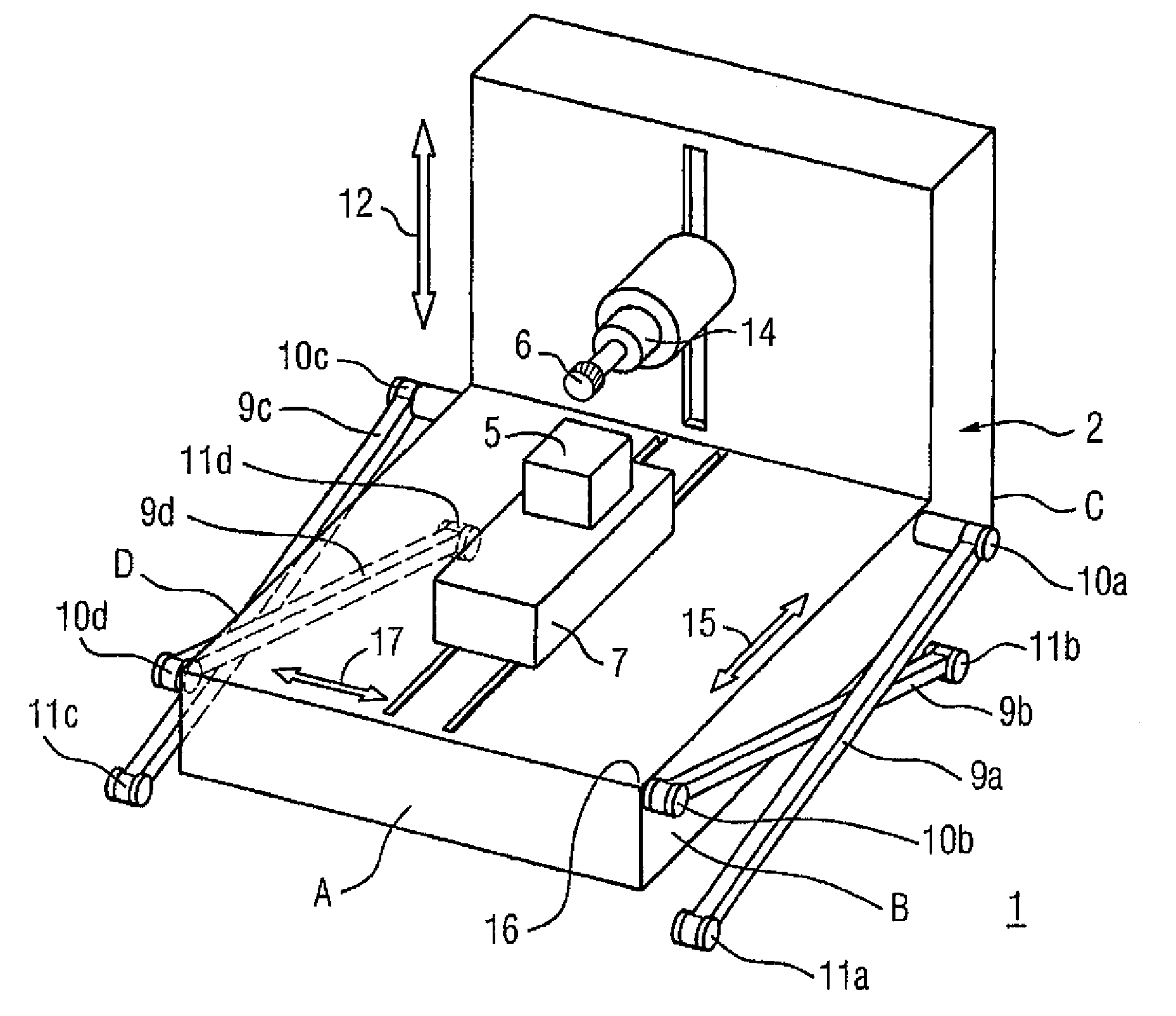
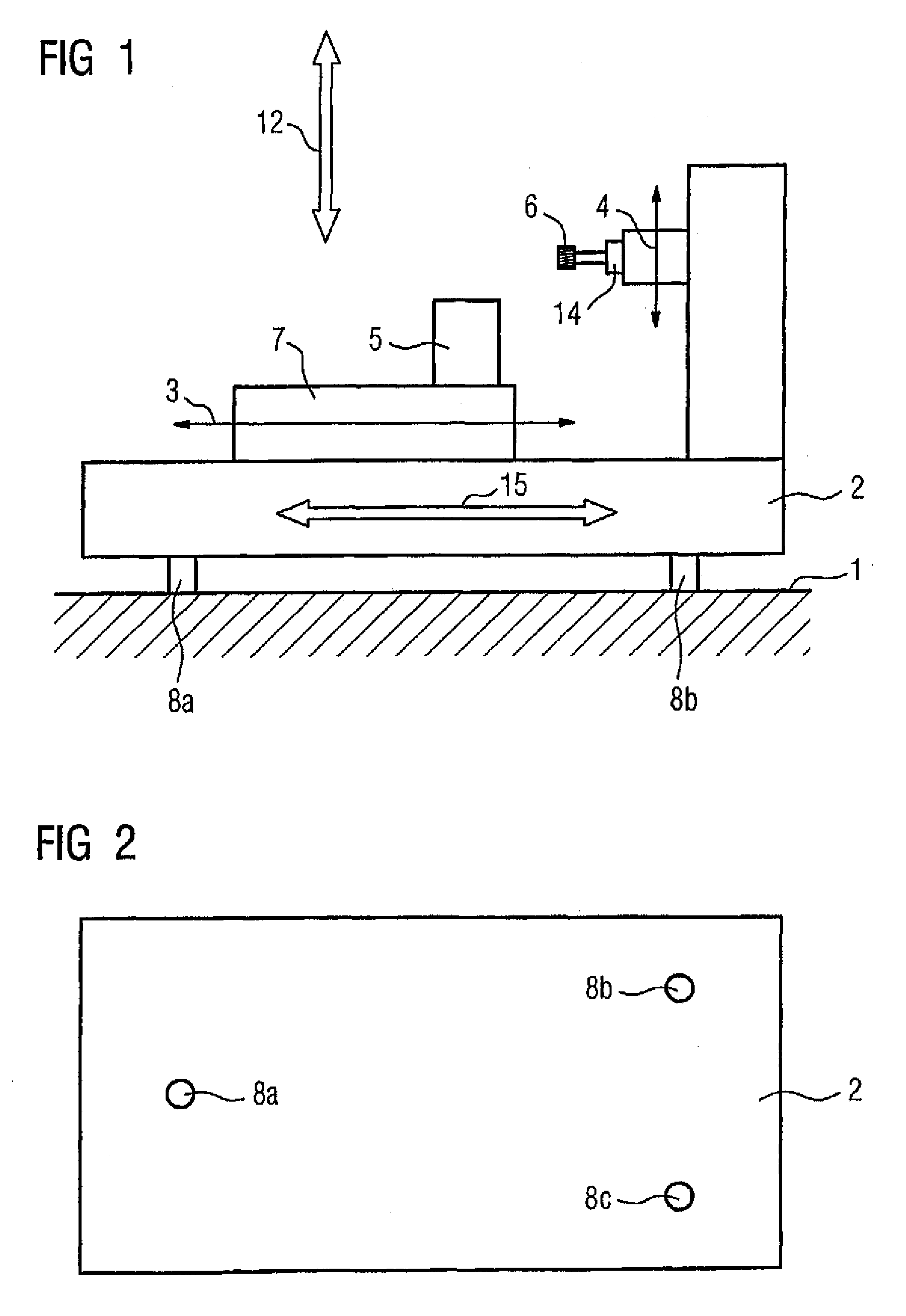
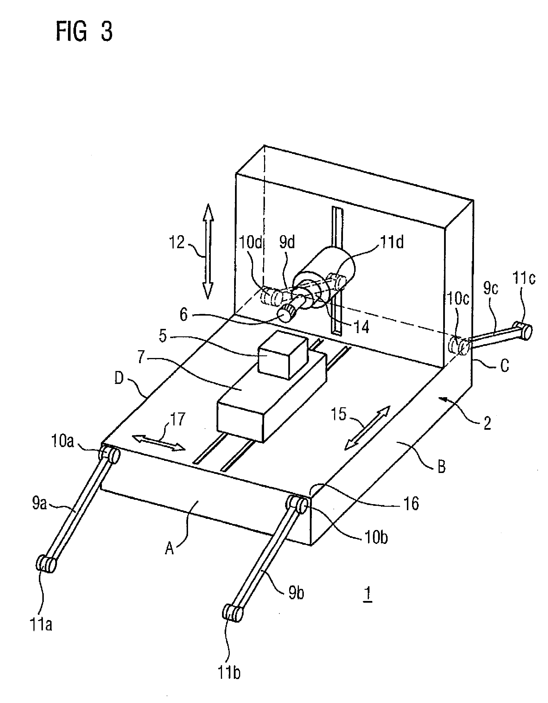
[0028]In FIG. 3, a machine tool according to the invention is illustrated diagrammatically in the form of a perspective view. The embodiment illustrated in FIG. 3 corresponds substantially to the commercially available embodiment described above in accordance with FIG. 1 and FIG. 2. For this reason, the elements are given the same reference numerals in FIG. 3 as in FIG. 1. The embodiment according to the invention in accordance with FIG. 3 is also set up on resilient mounting elements 8a, 8b and 8c in accordance with FIG. 1 and FIG. 2, but they are not expressly illustrated in FIG. 3. The four sides of the machine bed 2 in accordance with FIG. 3 are labeled A, B, C and D, with the side C, which is opposite the side A, and the side D, which is opposite the side B, not visible because of the perspective illustration. The essential difference between the machine tool according to the invention, in accordance with FIG. 3, and the machine tool in accordance with FIG. 1 is that in the emb...


PUM


Abstract

The invention relates to a machine, whereby at least one machine bed (2) of the machine is linked to a floor (1), by means of at least one support element (9a), said support element (9a) being pivotally mounted in relation to the machine bed (2) and the floor (1). The invention also relates to a support element (9a), for bearing a machine, whereby said support element (9a) comprises means (10a), by which the support element is pivotally linked to the machine and means (11a), by which said element is pivotally linked to the floor (1). The invention thus avoids horizontal movements of the machine bed.

Description

BACKGROUND OF THE INVENTION[0001]The invention relates to a machine.[0002]The invention furthermore relates to a support element for bearing the machine.[0003]The quality of machines, such as machine tools, production machines or robots, is severely impaired by disturbances, which can be introduced by way of vibrations in the floor on which the machine is standing, which may take the form of a shed floor or a platform. The disturbances are caused for example by forklift trucks, presses or other machines which cause the floor to vibrate and consequently have an adverse effect on the quality of manufacture. It is therefore conventional in a commercial context for the machines to be set on mounting elements on the floor and consequently for the machines to be separated from the floor.[0004]FIG. 1 shows, in the form of an example embodiment, a commercially available setting-up of this kind, for a machine tool. The two-axis machine that is illustrated in the example embodiment includes a...

Claims


Application Information

Patent Timeline
Patent Type & Authority Patents(United States)
IPC IPC(8): F16M3/00B23Q1/00B23Q1/01B23Q11/00F16F7/00F16F15/02F16F15/08F16M5/00
CPCB23Q1/0054B23Q1/01B23Q11/0032F16M5/00
Inventor HAMANN, JENSTRONDLE, HANS-PETERWEDEL, BERND
Owner SIEMENS AG
Features
  • R&D
  • Intellectual Property
  • Life Sciences
  • Materials
  • Tech Scout
  • Unparalleled Data Quality
  • Higher Quality Content
  • 60% Fewer Hallucinations
Learn More