Al technical title is built by PatSnap Al team. It summarizes the technical point description of the patent document.
a medical device and delivery system technology, applied in the field of delivery systems, can solve the problems of incorrect placement, system described by wilson, and inability to adjust the different components of the mechanism
Inactive Publication Date: 2010-09-21
ABBOTT LAB INC
View PDF72 Cites 211 Cited by
Summary
Abstract
Description
Claims
Application Information
AI Technical Summary
This helps you quickly interpret patents by identifying the three key elements:
Problems solved by technology
Method used
Benefits of technology
[0026]An actuator is disposed on the handle and is coupled to a rack-and-pinion assembly to move the sheath with respect to the inner member along the longitudinal axis from the first sheath position to the second sheath position. The rack-and-pinion assembly is configured to increase a deployment rate of movement for the sheath during at least a portion of movement of the actuator.
[0034]In another embodiment, the first gear pitch is defined by a first generally cylindrical portion of the rack gear. The rack gear has a first diameter and the second gear pitch is defined by a second generally cylindrical portion of the rack gear having a second diameter. The first diameter is greater than the second diameter. Rotation of the rack gear due to linear movement of the slider results in a greater rate of movement of the pinion.
[0036]In another embodiment, the rack gear is a bevel gear that has a generally conical circumferential surface. The second gear pitch is varied along a height of the conical surface. The plurality of teeth of the slider are disposed at varied heights along the elongate surface. Linear movement of the slider results in varied engagement of the plurality of teeth along the height of the circumferential surface to vary the rate a rotation of the rack gear and the rate of movement of the rack.
Problems solved by technology
As with other systems known in the art, the system described by Wilson does not permit re-adjustment of the different components of the mechanism after sterilization and shipment.
Shortcomings of delivery systems that operate in this manner is that the sheath is generally pulled back in a 1 to 1 ratio with the user's input, which for a longer stent requires a large amount of user input to release the stent which may lead to incorrect placement.
Method used
Image
Click on the blue label to locate the original text in one second.
Reading with bidirectional positioning of images and text.
Examples
Embodiment Construction
[0079]Reference will now be made in detail to the present preferred embodiments of the invention, examples of which are illustrated in the accompanying drawings. The method and corresponding steps of the invention will be described in conjunction with the detailed description of the apparatus. The methods and apparatus presented herein are used for delivering a medical device, such as a stent, stent graft or filter, to a desired location in a patient.
[0080]In accordance with the invention, it is possible and desired to provide a system for delivering such devices that is relatively inexpensive to manufacture and easy to use.
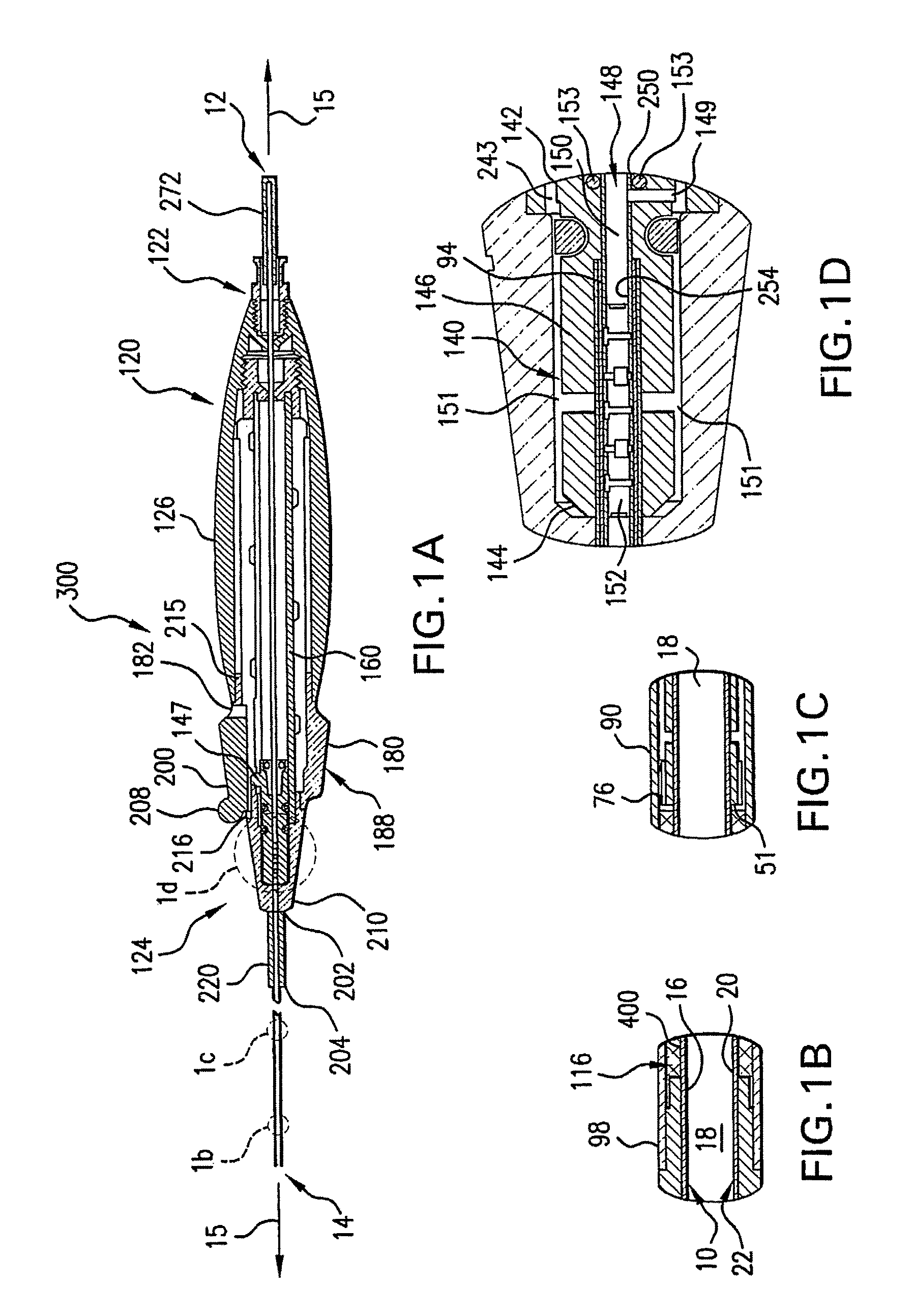
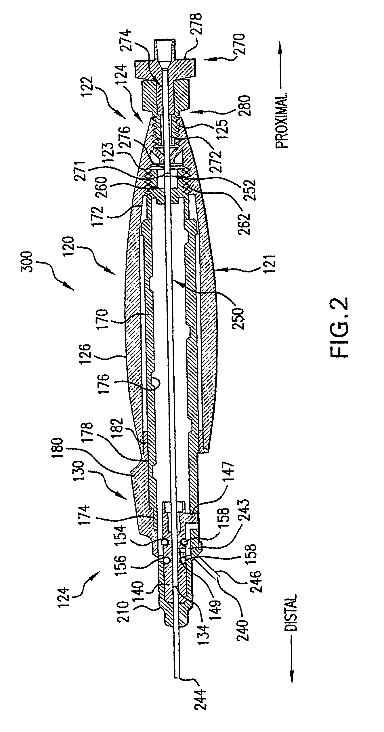
[0081]For purpose of explanation and illustration, and not limitation, an exemplary embodiment of the delivery system for a medical device in accordance with the invention is shown in FIGS. 1(a)-1(d) and is designated generally by reference character 1. This exemplary embodiment or portions thereof is also depicted in FIGS. 2, 4-6(a), 7-9, and 13-14(a). Additiona...
PUM
Property
Measurement
Unit
angle
aaaaa
aaaaa
internal diameter
aaaaa
aaaaa
internal diameter
aaaaa
aaaaa
Abstract
The invention is directed to a delivery system for delivering a medical device. The delivery system includes an inner member having a proximal end and a distal end. The inner member defines a longitudinal axis between the proximal end and the distal end. A tip is formed at the distal end of the inner member. A bumper is freely disposed on the inner member. The bumper has a proximal end and a distal end. A seat is defined between the tip and the distal end of the bumper. Additionally, a sheath is disposed about the inner member, the sheath having a proximal end and a distal end. The sheath is movable from a first sheath position substantially covering the seat, and a second sheath position axially offset to expose the seat. The invention also includes a handle in contact with the proximal end of the inner member.
Description
CROSS REFERENCE TO RELATED APPLICATION[0001]The present application is a continuation of U.S. patent application Ser. No. 11 / 479,607, filed Jun. 30, 2006, and U.S. patent application Ser. No. 11 / 479,644, filed Jun. 30, 2006, both of which claim priority to U.S. Provisional Application Ser. No. 60 / 695,498, filed Jun. 30, 2005. U.S. patent application Ser. No. 11 / 479,607, filed Jun. 30, 2006, and U.S. patent application Ser. No. 11 / 479,644, filed Jun. 30, 2006 are also continuation-in-part applications of U.S. patent application Ser. No. 10 / 932,964, filed Sep. 2, 2004, which claims priority to U.S. Provisional Application Ser. No. 60 / 499,075, filed Sep. 2, 2003. The aforementioned patent applications are all incorporated herein by reference in their entireties.FIELD OF THE INVENTION[0002]The present invention relates to a delivery system for delivery of one or more medical devices, such as a stent, stent-graft or filter. Particularly, the present invention is directed to a delivery sy...
Claims
Application Information
Patent Timeline
Application Date:The date an application was filed.
Publication Date:The date a patent or application was officially published.
First Publication Date:The earliest publication date of a patent with the same application number.
Issue Date:Publication date of the patent grant document.
PCT Entry Date:The Entry date of PCT National Phase.
Estimated Expiry Date:The statutory expiry date of a patent right according to the Patent Law, and it is the longest term of protection that the patent right can achieve without the termination of the patent right due to other reasons(Term extension factor has been taken into account ).
Invalid Date:Actual expiry date is based on effective date or publication date of legal transaction data of invalid patent.