Fuel cell cathode flow field

a technology of fuel cell and cathode flow, which is applied in the direction of fuel cell auxiliaries, fuel cells, electrochemical generators, etc., can solve the problems of reduced fuel cell performance, hot spots on the surface of the membrane, and cell deterioration, so as to improve fuel cell performance and improve fuel cell performance. , the effect of constant oxygen availability

Active Publication Date: 2010-11-23
LOOP ENERGY INC
View PDF11 Cites 19 Cited by
  • Summary
  • Abstract
  • Description
  • Claims
  • Application Information

AI Technical Summary

Benefits of technology

[0010]According to another aspect of the invention, there is provided a fuel cell separator plate comprising at least one of the flow channels described above. Optionally, the separator plate comprises multiple such cathode flow channels, wherein the flow channels are laterally spaced from each other by separator ribs. The flow channels collectively define a flow field that can be arrayed in a generally trapezoidal geometry. The separator ribs can have a substantially constant width to enable such trapezoidal geometry. The separator plate can further comprise partial separator ribs located at the inlet of each flow channel.

Problems solved by technology

Effects of oxygen starvation can be observed as a rapid decrease in cell voltage which in severe cases can cause a hot spot on the surface of the membrane.
As air flows along the flow field from inlet to outlet, the oxygen content in the air stream tends to be depleted and the air pressure tends to drop, resulting in reduced performance in the fuel cell.
While the straight-tapered channels of the PCT CA 02 / 00816 application do provide improved oxygen availability at the downstream end of the flow field, they do not achieve substantially constant oxygen availability throughout the flow field.

Method used


Image

  • Fuel cell cathode flow field
  • Fuel cell cathode flow field
  • Fuel cell cathode flow field

Examples


examples

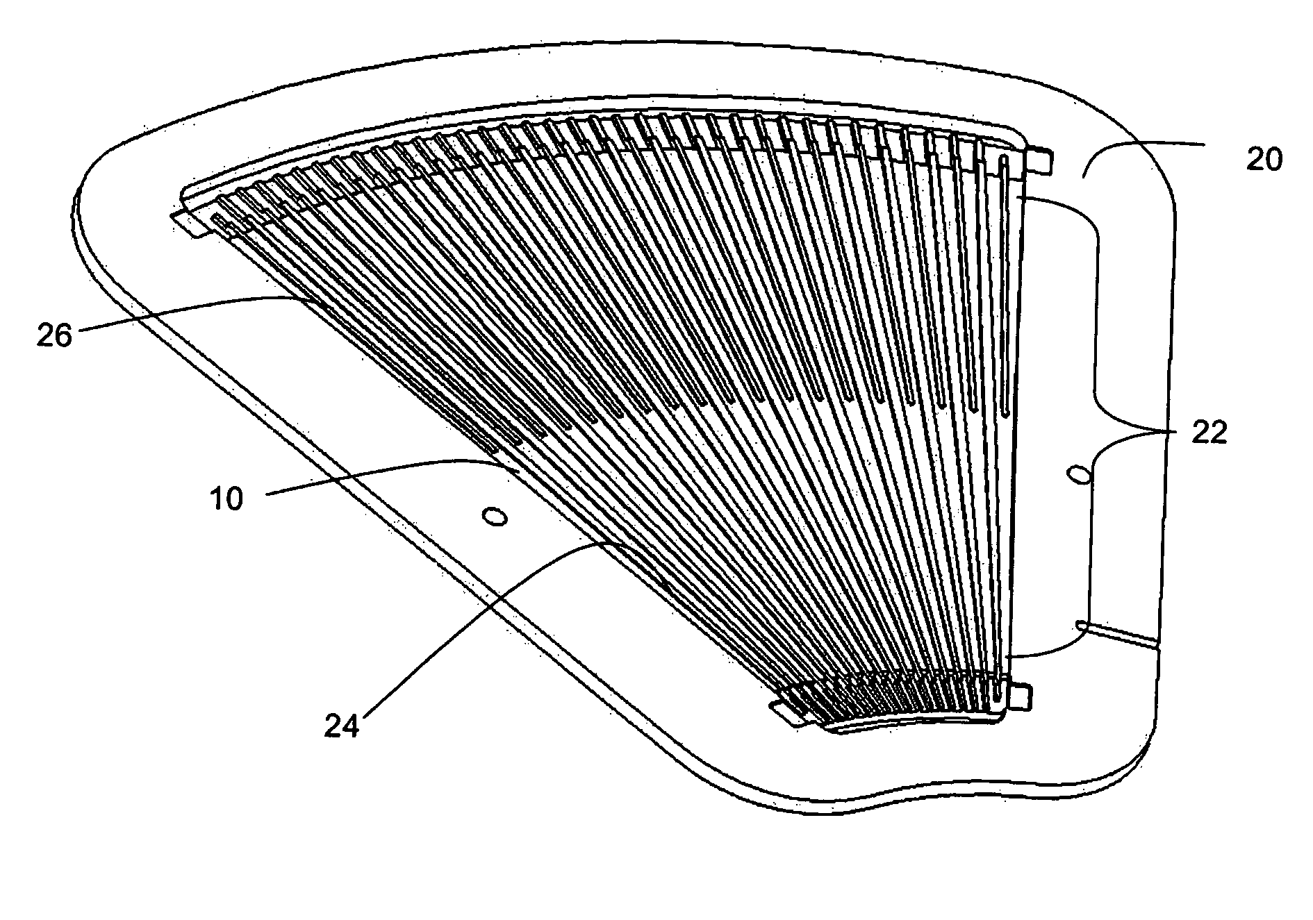
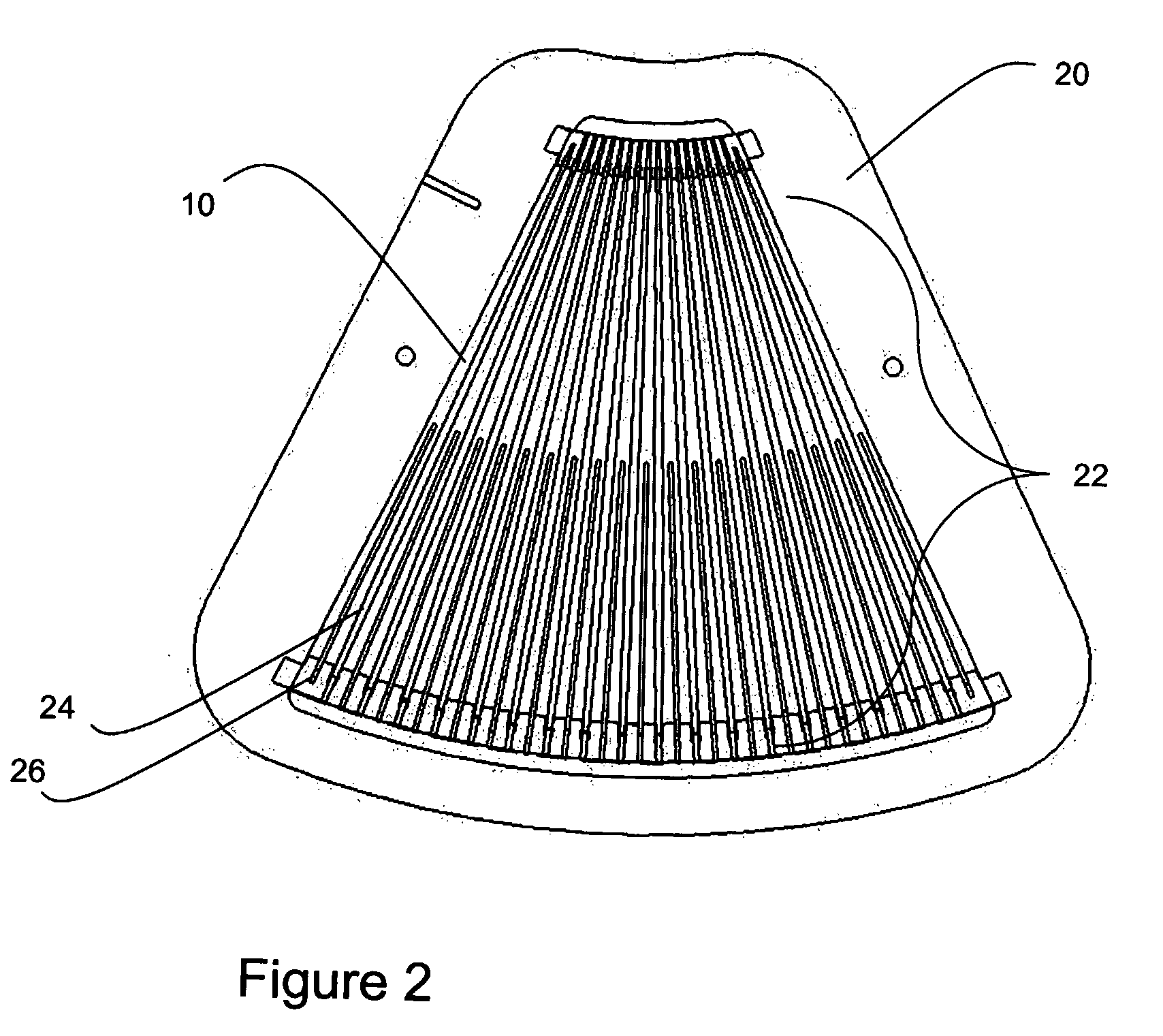
[0084]A prototype of the cathode separator plate 20 was tested using a Hydrogenics FCATS Test Station with varying current density, and under the following conditions:

[0085]

Air stoichiometry:2.5Fuel stoichiometry:1.5Relative Humidity (RH):80-100%Cell temperature:65° C.External Backpressure:None

[0086]MEA:[0087]Material: Gore PRIMEA Series 5510[0088]Design: 25 um thick, 0.4 Pt / 0.4 Pt C&A loading

[0089]GDL:[0090]Material: SGL Carbon 30BC[0091]Design: 0.32 mm thick, 77% porosity, cut to match MEA active area

[0092]Cathode Channel Profile:[0093]Material: SGL Carbon BBP 4 Graphite[0094]Design: Constant O2 Availability Channels at 5.7 mm->1.3 mm wide for a 1.295 Air Stoich setting, 19 channels delineating, 0.3 mm channel depth, 1-0.6 mm (Inlet-Outlet) land widths, 0.75 mm×50 mm (W×L) inlet channel ribs, and 86 cm2 active area

[0095]Anode Channel Profile:[0096]Material: SGL Carbon BBP 4 Graphite[0097]Design: 4 channels of dimensions 1 mm×1 mm×1052 mm (W×D×L), in a 13 pass serpentine arrangemen...


PUM

PropertyMeasurementUnit
lengthaaaaaaaaaa
widthaaaaaaaaaa
current densityaaaaaaaaaa

Abstract

A fuel cell cathode flow field has multiple channels each with a cross-sectional area that varies along the length of the channel such that oxygen availability at every lengthwise position along the channel is kept substantially constant for a given channel length and air stoichiometry ratio. Each channel comprises a flat floor with substantially constant depth and a pair of side walls extending upwardly from the floor; the side walls each taper inwards from channel inlet to outlet with a convex curve relative to the channel centreline. Achieving substantially uniform oxygen availability throughout the flow field results in substantially uniform current density throughout the flow field, which is desirable for efficient fuel cell operation and improved performance.

Description

CROSS REFERENCE TO RELATED APPLICATIONS[0001]This is the U.S. National Stage of International Application No. PCT / CA2005 / 001984, filed Dec. 29, 2005, which in turn claims the benefit of U.S. Provisional Patent Application No. 60 / 641,141, filed Jan. 5, 2005.FIELD OF THE INVENTION[0002]This invention relates generally to fuel cells and in particular to a method of manufacturing a cathode flow field for a fuel cell, and a fuel cell having same.BACKGROUND OF THE INVENTION[0003]In typical polymer electrolyte membrane (PEM) fuel cells, a membrane electrode assembly (MEA) is disposed between two electrically conductive separator plates. Oxidant and fuel flow fields provide means for directing the oxidant and fuel to respective electrocatalyst layers of the MEA, specifically, to an anode on the fuel side and to a cathode on the oxidant side of the MEA. A typical reactant fluid flow field has at least one fluid channel between an inlet and an outlet in which a fluid stream flows therethrough...

Claims


Application Information

Patent Timeline
Patent Type & Authority Patents(United States)
IPC IPC(8): H01M8/04
CPCH01M8/0265Y02E60/50
Inventor MONTIE, GREGREDLICH, RODNEY BRUCELEGER, DAVID EARL
Owner LOOP ENERGY INC
Why Eureka
Try Eureka