Multi-channel cooling die

a cooling die and multi-channel technology, applied in the field of cooling dies, can solve the problems of increasing the likelihood of inconsistencies arising in food product and structure blockages, increasing the area or floor space, and increasing costs, so as to reduce the average distance of extruder flow paths, reduce operational downtime, and reduce product path length variation.

Inactive Publication Date: 2007-10-02
MARS INC
View PDF12 Cites 19 Cited by
  • Summary
  • Abstract
  • Description
  • Claims
  • Application Information

AI Technical Summary

Benefits of technology

[0031]The invention provides extrudate flow channels that are angled outward in relation to the axial center-line of the die. The present invention thereby addresses the limitation of the prior art in providing even extrudate flow across all channels by ensuring minimal product path length variation. The present invention provides that the pitch circle diameter (PCD) of the extrudate channels at the inlet of the cooling die is smaller than the PCD at the die outlet. This difference in PCD may preferably be about 30%. This design reduces extrudate flow path average distance and standard deviation when compared with the prior art, and allows for reduced operational downtime due to blocked primary die-holes.
[0032]The present invention provides a cooling die assembly that is substantially simpler to assemble than the ‘stacked plate’ assemblies described in the prior art. The cooling section of the cooling die according to the present invention features a main housing (into which the smaller core members are bolted), a central cone, and an end plate. Assembly of the cooling die according to the invention is performed by first inserting the center cone into the main housing and then bolting on the end plate. This stage may be carried out in approximately 10 minutes. Dismantling is equally simplified. At the conclusion of a production run, the end plate is removed followed by the center cone. A special cone removal device may preferably be supplied to simplify this task even further. Any remaining extrudate in the die can then be easily removed using high-pressure water or, if extrudate is too hard for water to be effective, a suitable tool may be provided to remove hard extrudate.
[0033]This task is simplified in the present invention because one entire side of the extrudate channel is removed when the inner cone is taken out. This means that the extrudate is not constrained on all sides by the die itself, allowing easy insertion of cleaning tools.
[0034]The cooling die according to the present invention provides greater physical isolation between the extrudate and coolant flow channels than the ‘stacked plate’ designs of the prior art. Therefore, physical wear of the various components of the cooling die is significantly less likely to allow e.g. cross-contamination between the extrudate and the coolant. This means that parts can endure significantly more wear without impacting product quality or die integrity. The running cost of the die according to the present invention is therefore likely to be significantly lower.
[0035]Preferably, one cooling water channel cools the entire length of one side of the product channel. The result is significantly improved evenness of heat transfer and hence product quality.

Problems solved by technology

This has a number of adverse consequences.
For instance, longer cooling dies increase the likelihood of inconsistencies arising in the food product and structure blockages occurring in the cooling die.
Also, such dies obviously take up more area or floor space of the production plant, which in turn increases costs.
The smooth surface of the tubes can be damaged during the cleaning process (due to their length), which may result in irregular loading of individual tubes from the extruder as a consequence of increased surface roughness (and back pressure) at individual tubes.
Also, where one of the tubes is damaged to an extent that it no longer provides a flow path for the molten extrudate, it may be necessary to replace the entire cooling die or individual tubes.
The replacement process is potentially time-consuming and labour intensive, as the individual tubes are received in airtight manner at the end plates of the cylindrical shell.
However there are some disadvantages associated with this particular design, outlined as follows:
Unless additional coolant flow restriction elements are employed to achieve constant and equivalent flow through all cooling medium channels, such design will have adverse consequences for product quality and consistency, product exiting the cooling die would tend to be heterogeneous with the portion of product closer to the center of the cooling die being slightly more expanded (due to poorer cooling) than the product further from the center.
In addition to this, uneven heat transfer can result in some product channels running more slowly than others.
This results in product passing through the cooling die at various residence times. Some product may therefore be over expanded while other product is not sufficiently expanded.
An example of operational difficulties that may arise due to this effect is that the flow in some channels may stop completely while the flow in the others increases to an extent where it does not receive adequate cooling, adversely affecting product quality.
This in turn leads to the development of burnt product that can lead to downgraded product or blocked primary die holes.
A disadvantage associated with this form of construction is that assembly of this die time-consuming, and requires significant operator skill to position all the plates correctly and tension the clamping bolts.
Dismantling of the cooling die for cleaning purposes may also take significant time, particularly if the product remaining in the cooling die at the conclusion of a run solidifies in the channels, effectively bonding the plates together.
Such solidified product may potentially be difficult and time-consuming to remove.
Slight wear on the surfaces of the plates could result in extrudate leaking into coolant channels, or to the outside, or coolant leaking into extrudate channels, or to the outside.
Even small levels of leakage create quality or stability problems and so damaged plates are replaced regularly.

Method used


Image

  • Multi-channel cooling die
  • Multi-channel cooling die
  • Multi-channel cooling die

Examples


Embodiment Construction

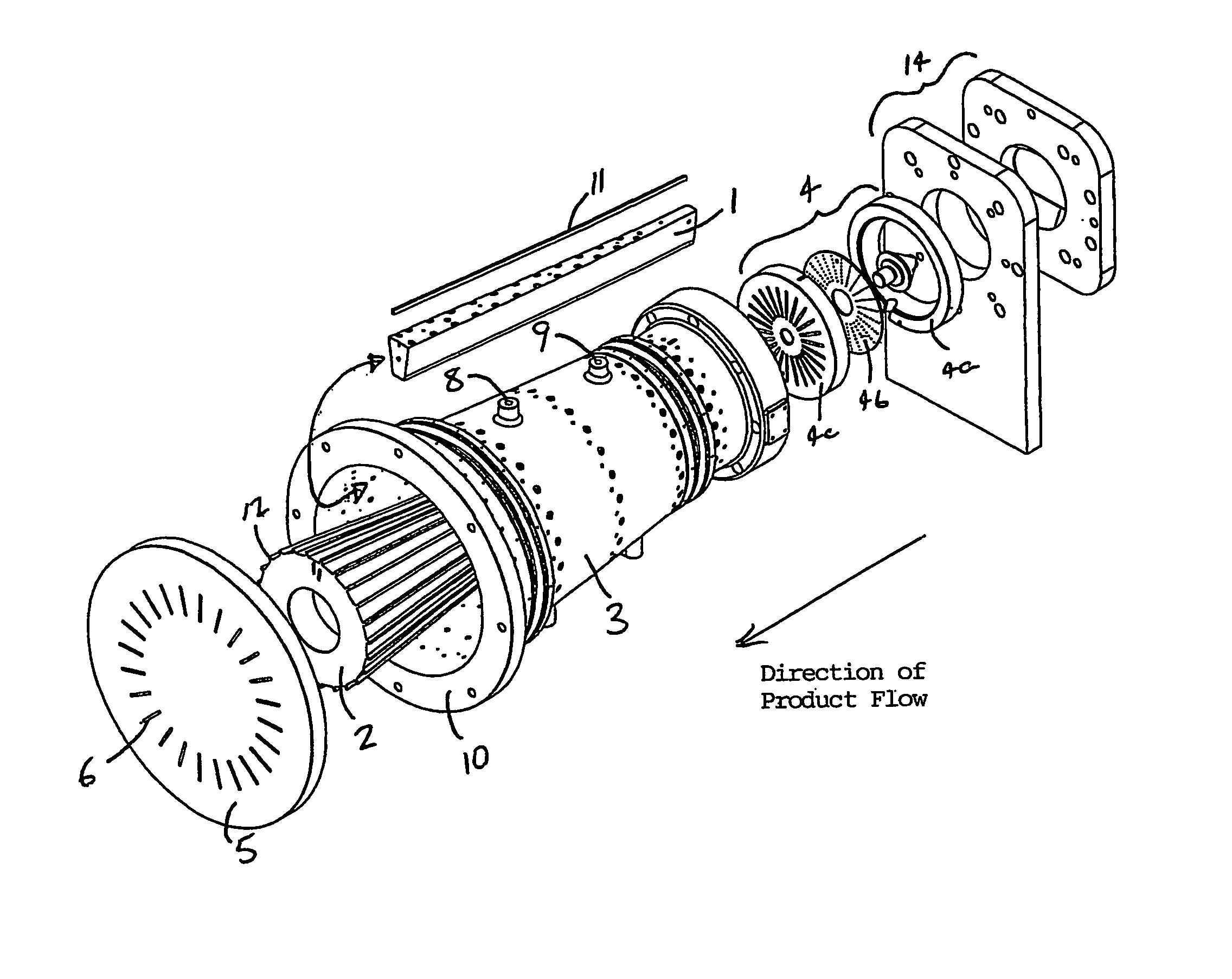
[0048]In order to produce extruded food products, such as fibrous meat analogues, one requires an extruder with the ability to impart shear and pressure on the ingredient formulation and convey said material to the cooling die. The extruder may contain one or more screws. These are well known and will not be described here.

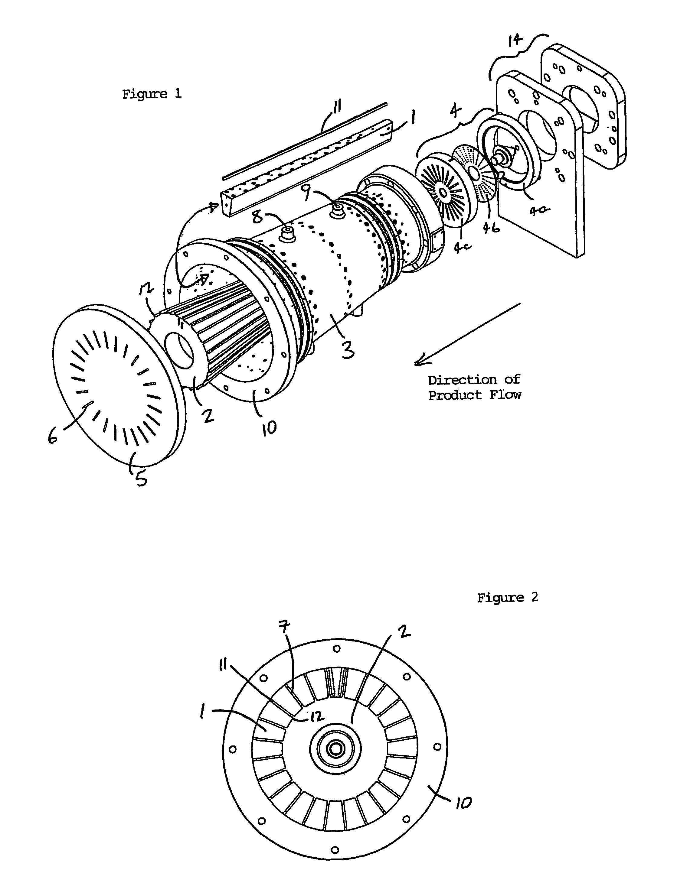
[0049]A cooling die assembly, in accordance with the invention, for use at the delivery end of a high moisture proteinaceous food extruder, is shown in an exploded isometric view in FIG. 1. The die assembly essentially comprises a multi-piece die body consisting of a plurality of cooling wedges 1 that are arranged radially around a central core 2. This arrangement is encased within a tubular restraining sheath 3. Extrudate flow is directed into the inlet end of the die from the extruder via a flow distribution device 4, consisting of a diverging cone 4a, a holeplate 4b and a slotted plate 4c. The distribution device 4 is designed to ensure even extrudate flow into...


PUM

PropertyMeasurementUnit
temperatureaaaaaaaaaa
lengthaaaaaaaaaa
widthaaaaaaaaaa

Abstract

A cooling die, for use in the manufacture of extruded food products, the cooling die including: a plurality of core members forming a main body portion of the cooling die between die inlet and outlet ends and arranged about an axis of the die in neighboring relationship; a plurality of extrudate flow channels extending through the cooling die from the inlet end to the outlet end, defined by gaps between neighboring ones of said core members; at least one bore in each said core member through which coolant may flow; an enclosing structure adapted to secure the core members against radial movement relative to the die axis; means for connecting the cooling die to an outlet of a food extruder, a cooling fluid source and a cooling fluid receptacle; and extrudate flow distribution means, located adjacent the inlet end, adapted to direct extrudate from the outlet of the food extruder into selected ones of said extrudate flow channels.

Description

CROSS-REFERENCE TO RELATED APPLICATIONS[0001]This application is a national stage filing of PCT / AU02 / 00899 filed Jul. 5, 2002, claiming priority to Australian Application No. PR6219 filed Jul. 6, 2001.TECHNICAL FIELD[0002]This invention relates to cooling dies for use in association with food extruders in the manufacture of texturised protein food products.[0003]In particular, the present invention relates to a cooling die for use in the manufacture of an extruded food product that has the appearance of fibrous meat pieces such as fish, chicken, lamb or beef. The cooling die is attachable to the outlet of an extruder which may contain one or more screws and feeds molten extrudate to said cooling die at a temperature between 110° and 180° C.BACKGROUND OF THE INVENTION[0004]Various protein texturisation processes have been used for some time in the manufacture of various food products, such as in the manufacture of sausages, kamaboko, meat analogs and seafood analogs. A fibrous textur...

Claims


Application Information

Patent Timeline
Patent Type & Authority Patents(United States)
IPC IPC(8): B29C47/12B29C47/86A22C7/00A23P1/12B29C48/05B29C48/08B29C48/30B29C48/86B29C48/87
CPCA23P1/12B29C47/86B29C47/0021B29C47/0014A23P30/20B29C48/05B29C48/08B29C48/86B29C48/87
Inventor HOWSAM, STUART
Owner MARS INC
Why Eureka
Try Eureka