Rotary electric machine and electric wheelchair mounted with rotary electric machine

a technology of rotary electric machines and electric wheelchairs, which is applied in the direction of magnetic circuit rotating parts, electric devices, magnetic circuit shapes/forms/construction, etc., can solve the problems of energy loss, fear of being separated during the assembly process, and increase the cost of the electric wheelchair, so as to reduce the loss of induction current

Inactive Publication Date: 2009-05-05
YAMAHA MOTOR CO LTD
View PDF41 Cites 18 Cited by
  • Summary
  • Abstract
  • Description
  • Claims
  • Application Information

AI Technical Summary

Benefits of technology

[0016]The present invention was conceived in consideration of the above prior art, and an object of the present invention is to provide a rotary electric machine capable of minimally suppressing the induction current loss even if teeth are fixed through fitting portions and also to provide an electric wheelchair mounted with such rotary electric machine.
[0027]According to the rotary electric machine of the present invention of the characteristics mentioned above, a plurality of fitting portions formed to the coil wind-up portions, each having substantially the constant width, of the teeth are arranged along the center line of this wind-up portion. Therefore, at the time of high flux density in the coil wind-up portion, the magnetic flux flows in the same direction as that of the center line thereof, and by arranging the plural fitting portions in alignment with the same direction as that of the center line, the variation in the magnetic flux flowing the closed circuit formed between the fitting portions can be significantly suppressed, and hence, the loss of energy can be also reduced. In addition, the formation of the plural fitting portions can contribute to the assembling performance of the rotary electric machine with improved strength against conveyance, transportation or like.
[0028]Moreover, according to the other features of the present invention, since the fitting portions are formed at portions apart from the head portion or insert portion of the tooth by not less than ½ width of the wind-up portion thereof, the disturbance of the magnetic flux at the portions near the head portion, the stator yoke core or yoke insert portion can be significantly suppressed and the loss of energy can be also suppressed.
[0029]The rotary electric machine formed according to the present invention has a compact, flat and lightweight structure with the small loss of energy can be provided.
[0030]Furthermore, each of the fitting portions formed to the magnetic steel plates has protruded and recessed portions, and the protruded portion of one steel plate is fitted to the recessed portion of the other adjacent steel plate to thereby easily laminate and fix the respective steel plates together.
[0038]According to this aspect, the electric wheelchair mounted with the improved rotary electric machine having compact structure and high output performance can be provided.

Problems solved by technology

However, in such arrangement, it was troublesome to assemble the separated steel plates 2a, which involved cost increasing, thus being disadvantageous.
However, in the case where the respective steel plates 2a are fixed by using the half pierce member, when the fixing is made only at one portion, there is a fear of being separated during its assembling process because of no sufficient strength.
In addition, although these steel plates 2a are insulated by insulating films, such insulating films may be broken by the formation of the half pierce member, which may result in short-circuiting, and the respective steel plates 2a become electrically connected state.
Accordingly, if such half pierce members are located at several portions, a closed circuit will be presented through these half pierce members, and a magnetic flux crosses this closed circuit and then the induction current passes, resulting in the cause of energy loss, thus being inconvenient and disadvantageous.
Further, the holes for fixing the respective core lamination plates corresponding to the steel plates of the teeth (tooth) are formed in the above prior art publication, but these holes are through holes, which are not for causing the induction current.

Method used


Image

  • Rotary electric machine and electric wheelchair mounted with rotary electric machine
  • Rotary electric machine and electric wheelchair mounted with rotary electric machine
  • Rotary electric machine and electric wheelchair mounted with rotary electric machine

Examples


first embodiment

[0061]The first embodiment of the present invention is represented by FIGS. 1 to 12.

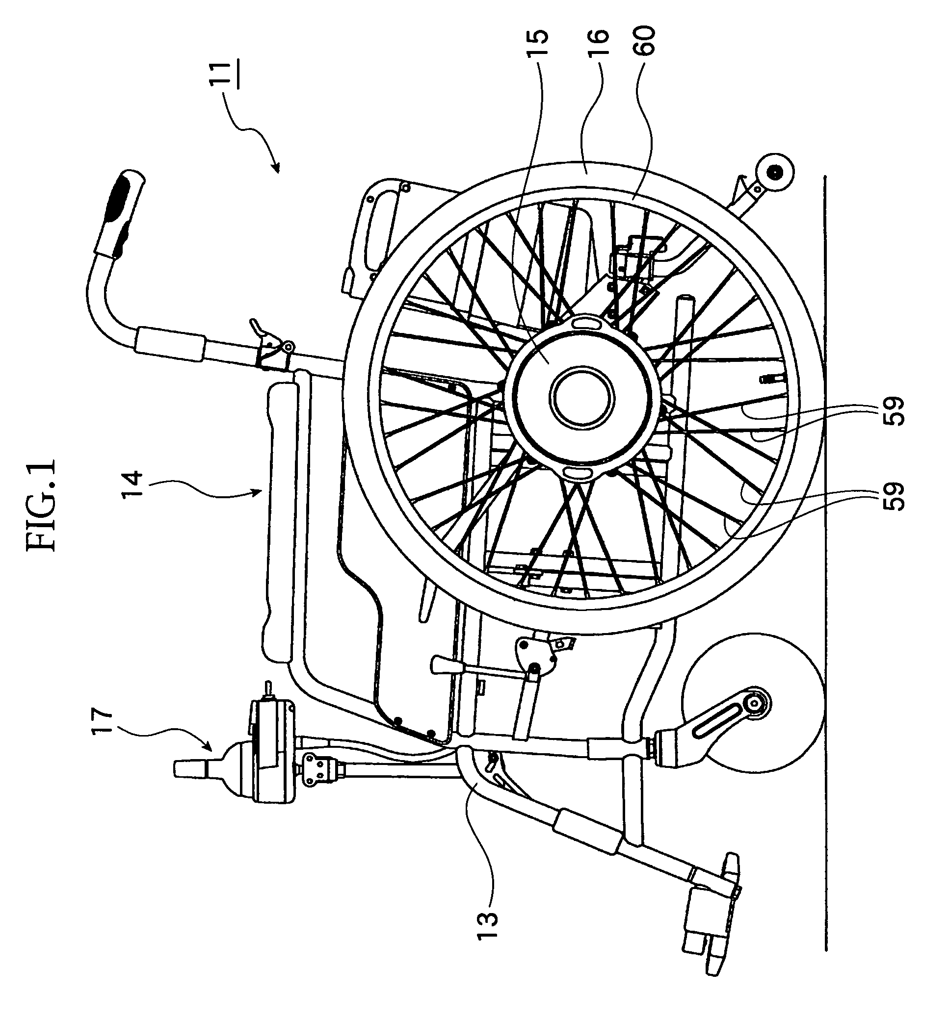
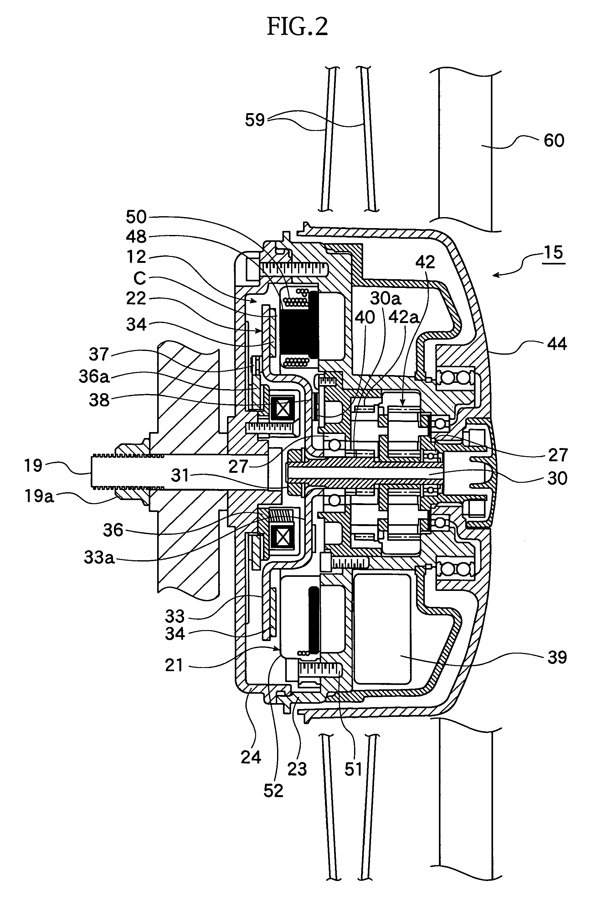
[0062]With reference to FIG. 1, reference numeral 11 denotes an electric wheelchair or electrically powered wheelchair mounted with an electric motor 12 as a “rotary electric machine” according to the present invention, and the electric wheelchair is driven and traveled by the driving force of the electric motor 12.

[0063]The electric wheelchair 11 is provided with a frame 13 as a framework of a vehicle (electric wheelchair body), a seat 14 on which a user sits and a pair of driving wheel units 15 in which the electric motors 12 are mounted. When an operation unit 17 of the electric wheelchair 11 is operated, the paired driving wheel units 15 are driven so as to drive driven wheels 16 by predetermined amount (distance). The driven wheels 16 are operated independently, and by the operation of the operation unit 17, the driven wheels 16 are changed in their rotating directions and driven speed, respecti...

second embodiment

[0091]FIGS. 13 and 14 represent the second embodiment of the present invention.

[0092]In this second embodiment, the structure of the fitting portion differs from that of the first embodiment.

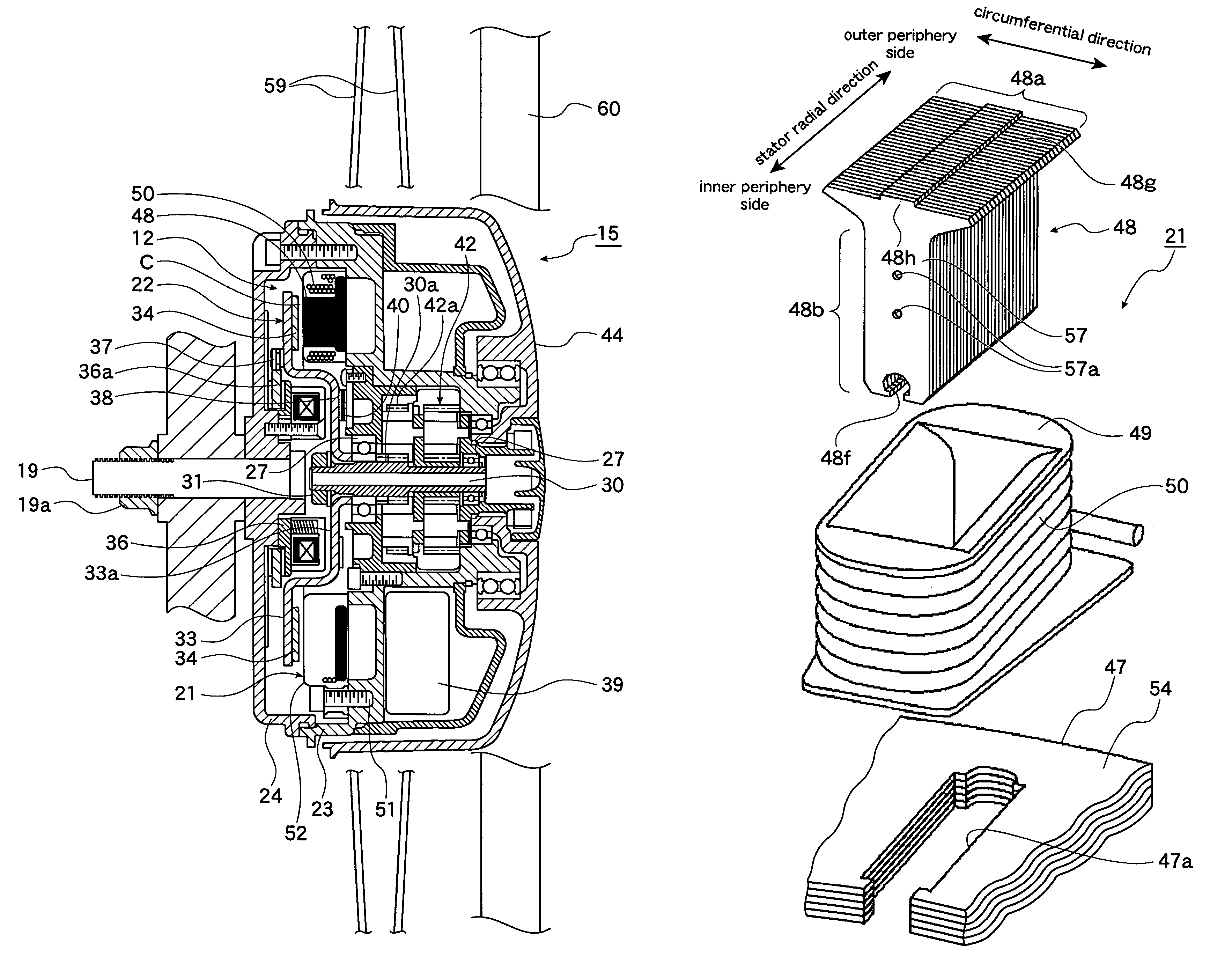
[0093]That is, in the first embodiment, the half pierce portion 57a has substantially the circular shape as a front view, but in this second embodiment, this portion has a rectangular shape in the direction along the center line O1 of the wind-up portion 48c as shown in FIG. 13, and the respective magnetic plates 57 are caulked and fixed together by V-shaped caulking portions 57f each showing V-shape as shown in FIG. 14 in cross-section. These two caulking portions 57f are arranged along or on the center line O1 of the wind-up portion 48c as like as the half pierce portions 57a of the first embodiment.

[0094]The structures other than the above are substantially the same as those in the first embodiment, so that explanation thereof is omitted herein.

[0095]It is to be noted that the present inventi...


PUM


Abstract

A rotary electric machine comprises a stator including a plurality of teeth which are wound up by coils and a stator yoke core connecting the respective teeth, and a rotor provided with magnets disposed so as to oppose to the teeth, respectively, with a space therebetween. Each of the teeth (tooth) is formed into T shape by laminating a plurality of magnetic steel plates and has a head portion and a leg portion, the head portion being a wider portion of the T-shape which is opposed to the magnet, the leg portion including a coil wind-up portion which has a substantially constant width and an insert portion which is inserted into the stator yoke core, and the coil wind-up portion is formed with a plurality of fitting portions for fitting and fixing the laminated magnetic steel plates together, the fitting portions being arranged so as to align along a center line of the coil wind-up portion.

Description

CROSS-REFERENCE TO RELATED APPLICATIONS[0001]The present application is based on and claims priority under 35 U.S.C. § 119 to Japanese Patent Application No. 2005-210497, filed on Jul. 20, 2005.BACKGROUND OF THE INVENTION[0002]1. Field of the Invention[0003]The present invention relates to a rotary electric machine capable of suppressing an energy loss due to induction or induced current by improving teeth of a stator and also relates to an electric wheelchair (or electrically powered wheelchair) mounted with such rotary electric machine.[0004]2. Related Art[0005]In a known art, as such a rotary electric machine, there has been provided an axial gap type rotary electric machine as shown, for example, in FIGS. 16 to 19.[0006]Referring to FIGS. 16 to 19, the rotary electric machine is provided with a stator 3 formed with teeth 2 and a rotor provided with a plurality of magnets (permanent magnets), not shown, in which the stator and the rotor are arranged with a gap in a rotation axis ...

Claims


Application Information

Patent Timeline
Patent Type & Authority Patents(United States)
IPC IPC(8): H02K1/22A61G5/04H02K1/14H02K1/18H02K7/116H02K7/14
CPCA61G5/045H02K1/148H02K1/2793H02K7/14B60L15/20Y02T10/641A61G2203/14A61G5/1032B60L2200/34B60L2220/44B60L2240/421B60L2250/24Y02T10/7275Y02T10/642A61G2005/1054Y02T10/72A61G5/1054Y02T10/64H02K1/2795
Inventor NAITOU, SHINYAHINO, HARUYOSHI
Owner YAMAHA MOTOR CO LTD
Why Eureka
Try Eureka