Blade for a wind Turbine Rotor

a technology for wind turbines and rotors, applied in the direction of liquid fuel engines, vessel construction, marine propulsion, etc., can solve the problems of low production and large loads

Active Publication Date: 2009-09-17
LM GLASSFIBER
View PDF5 Cites 19 Cited by
  • Summary
  • Abstract
  • Description
  • Claims
  • Application Information

AI Technical Summary

Benefits of technology

[0020]Alternatively, the at least one root segment with airfoil profile may have a separately mounted segment. This embodiment is advantageous in that said segments may be used for existing wind ...

Problems solved by technology

This again results in problems when having to mount the blade to the hub, and, moreover, this causes great loads when the blade is mounted, such as storm loads, due to the large surface ar...

Method used


Image

  • Blade for a wind Turbine Rotor
  • Blade for a wind Turbine Rotor
  • Blade for a wind Turbine Rotor

Examples


first embodiment

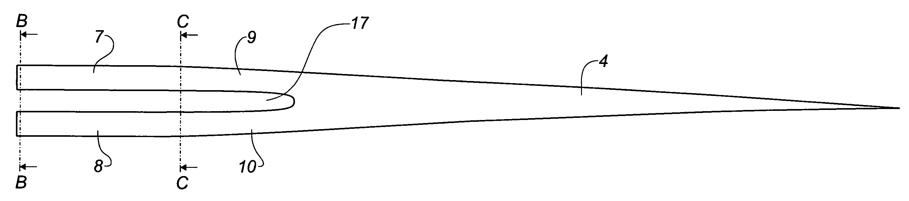
[0030]FIG. 3A shows a blade according to the invention, where the blade is seen towards the leading edge 5, while FIG. 3B shows a section along the line BB and FIG. 3C shows a section along the line CC of FIG. 3A, where section CC is situated at the transition between the root area 2 and the transition area 3. According to this embodiment, the root area 2 is divided into a first root segment 7 and a second root segment 8, and the transition area 3 is divided into a first transition segment 9 and a second transition segment 10. The two transition segments 9 and 10 are joined at the transition between the transition area 3 and the airfoil area 4. As a result, there is a gap 17 between the segments. Additionally, the segments may be mutually connected by means of stiffening means arranged in the space 17 between the segments. These stiffening means may for example be provided as a grid construction of e.g. steel and may further be provided with for example a so-called drag reduction pr...

third embodiment

[0035] shown in FIG. 5, the first and the second root segments 72, 82 as well as the first and the second transition segments 92, 102 have symmetric profiles. The profiles are shown with the chord planes parallel to the direction of rotation of the blade, however, the profiles may preferably be angled with respect to the direction of rotation, where the angle is selected based on maximising the lift.

[0036]As seen from FIG. 5B, both the first root segment 72 and the second root segment 82 extend beyond the circular profile of the conventional root part 12. Finally, it should be noted that the root segments of the embodiment shown In FIGS. 4 and 5 as well as the embodiment shown in FIG. 3 each merge into a corresponding transition segment (92, 93, 102, 103), said segments joining to form a common profile at the transition between the transition area 3 and the airfoil area 4.

fourth embodiment

[0037]FIG. 6 shows the blade, where the first root segment 73 and the second root segment 83 are joined at the mounting area 22. As seen in FIG. 6B, the mounting area 22 is circular and contains mounting holes 11, the blades being secured to the hub by bolts through said holes. The blade is thus adapted to conventional hubs and can thus replace existing blades on already installed wind turbines during a renewal.


PUM


Abstract

A blade (1) for a rotor of a wind turbine having a substantially horizontal′ rotor shaft, said rotor comprising a hub, from which the blade extends substantially radially from said rotor when mounted. The blade (1) has a chord plane (K) extending between the leading edge (5) and the trailing edge (S) of the blade (1). The blade (1) comprises a root area (2) closest to the hub, an airfoil area (4) furthest away from the hub and a transition area (3) between the root area (2) and the airfoil area (4), and comprises a single airfoil along substantially the entire airfoil area (4). The blade (1) comprises at least a first root segment (7) and a second root segment (8) along substantially the entire root area (2), said segments being arranged with a mutual distance, as seen transverse to the chord plane (K). At least one of the root segments (7, 8) has an airfoil profile.

Description

TECHNICAL FIELD [0001]The present invention relates to a blade for a rotor of a wind turbine having a substantially horizontal rotor shaft, said rotor comprising a hub, from which the blade extends substantially radially when mounted, said blade comprising a chord plane extending between the leading edge and the trailing edge of said blade, and said blade comprising a root area closest to the hub, an airfoil area furthest away from the hub and a transition area between the root area and the airfoil area, and said blade comprising a single airfoil along substantially the entire airfoil area.BACKGROUND ART[0002]Ideally, a blade of the airfoil type is shaped like a typical aeroplane wing, where the chord plane width of the blade as well as the first derivative thereof increase continuously with decreasing distance from the hub. This results in the blade, ideally being comparatively wide in the vicinity of the hub. This again results in problems when having to mount the blade to the hub...

Claims


Application Information

Patent Timeline
IPC IPC(8): F03D1/06
CPCF03D1/0641F03D1/0658F01D5/12F05B2260/97Y02E10/721F05B2240/301Y02E10/72
Inventor GRABAU, PETER
Owner LM GLASSFIBER
Why Eureka
Try Eureka