Injection-molded plastic guide rail

a technology of injection molding and guide rails, which is applied in the field of rear window shades, can solve the problems of unsatisfactory relative movement of plastic parts and aluminum guides, inability to adjust the friction between plastic guides and aluminum guides, and certain difficulties when integrating the guide rail into the inside lining, etc., and achieves constant width and a favorable force gradient

Active Publication Date: 2007-03-13
BOS
View PDF10 Cites 18 Cited by
  • Summary
  • Abstract
  • Description
  • Claims
  • Application Information

AI Technical Summary

Benefits of technology

[0005]It is an object of the present invention to provide an improved guide rail arrangement for motor vehicle window shades that eliminates the foregoing disadvantages of the prior art.
[0007]The significant advantage of this arrangement can be seen, among other things, in that injection-molding tools with a drawable core are not required for manufacturing various designs of the outer part. Since the material of the outer part can be elastically deformed, the injection-molded part can simply be removed from the core that produces the undercut groove during the injection-molding process. This significantly reduces the costs of the manufacturing method. It is possible, in particular, to integrate the outer part into a section of the inside lining of the motor vehicle. The support part itself does not contain undercut grooves so that its manufacture does not require injection-molding tools with movable cores.
[0009]The material of the outer part preferably is selected from a group of thermoplastics. This makes it possible to achieve the desired resilience, wherein the support part counteracts a possible deformation over time. For this purpose, the support part, which may be manufactured from a light metal, contains a region that laterally supports, at least sectionally, the guide groove on flanks in the installed condition. In the simplest design, the support part contains a groove that is U-shaped and has parallel flanks.
[0013]In order to achieve a favorable force gradient that does not exert a disadvantageous bursting effect upon the two parts when the guide element of the window shade moves through the guide groove, it is advantageous if the web extends at an acute angle relative to a plane that is defined by the slot and extends through the slot.
[0014]In addition to the two interconnected parts, a support part of a less deformable material may be provided, wherein this support part is attached to the two interconnected parts. The support part serves to prevent the molded plastic parts from distorting. Such a distortion may be caused by aging or age-related shrinkage. The support parts stabilize the groove and ensure that the slot of the guide groove maintains a constant width over its entire length.

Problems solved by technology

Long-term usage has revealed that the combination of the plastic part and an aluminum rail is not rattle-free under all conditions.
The friction between the plastic guide elements and the aluminum guide rail is not suited for optimal relative movement.
In addition, certain difficulties can occur when integrating the guide rail into the inside lining.

Method used


Image

  • Injection-molded plastic guide rail
  • Injection-molded plastic guide rail
  • Injection-molded plastic guide rail

Examples


Embodiment Construction

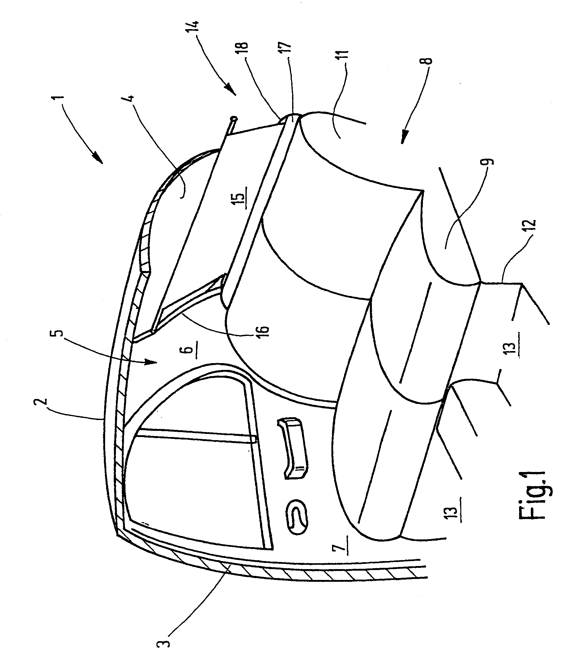
[0024]Referring now more particularly to FIG. 1 of the drawings, there is shown the inside of a passenger car having a rear window shade in accordance with the invention The passenger car includes a body section 1 that includes a roof 2, from which a B-column 3 laterally extends downward to a floor group, not shown. The roof 2 transforms into a rear window 4 on its rear edge. The rear window 4 laterally ends on a C-column 5 that is spaced apart from the B-column 3. The C-column 5 carries the inside lining 6.

[0025]As will be understood by persons skilled in the art, between the B-column 3 and the C-column 5, a right rear door 7 is conventionally hinged to the B-column 3. A rear bench 8 consisting of a seat 9 and a back rest 11 is arranged at the height of the right rear door 7. The rear seat 9 lies on a base surface 12 that forms part of the floor group, wherein a certain leg room 13 is created in this floor group in front of the rear seat 9.

[0026]A rear window shade 14 is mounted on...


PUM


Abstract

A window shade arrangement for motor vehicles that includes plastic injection molded guide rails designed such that they may be formed with injection tools that do not require moveable cores for forming guide grooves therein. In one embodiment, the guide rail includes an outer part (41) formed with a guide groove and a support part (42) made from less deformable material than the outer part for preventing widening of and deforming of the guide groove during usage. In another embodiment, the first and second molded parts are interconnectable to define the guide groove.

Description

BACKGROUND OF THE INVENTION[0001]DE 100 57 759 A1 describes a rear window shade for motor vehicles. This rear window shade comprises a winding shaft that is rotatably supported underneath a rear window shelf, wherein one edge of the strip-shaped shade is fixed the winding shaft. The strip-shaped shade is cut into an approximately trapezoidal shape with its other end distant to the winding shaft fixed to a draw-out rod Movement of the draw-out rod is laterally guided in two guide rails that are either bonded to the inner side of the rear window or hidden in the car body behind the lining of a C-column. Elastically bendable thrust elements for moving the draw-out rod are guided in the guide rails in a buckle-proof fashion.[0002]The guide rails consist of an extruded aluminum profile with a continuous undercut groove. The groove is composed of a section with a circular cross section and a section with a rectangular cross section, wherein the section with a rectangular cross section is ...

Claims


Application Information

Patent Timeline
Patent Type & Authority Patents(United States)
IPC IPC(8): B60J3/00B60J1/18B60J1/20
CPCB60J1/2027B60J1/208B60J1/2052B60J1/18
Inventor HANSEN, MELFWEINBRENNER, HARRYWALTER, HERBERTBUHL, OLAFMAIER, MATTHIAS
Owner BOS
Why Eureka
Try Eureka