Deflector mirror, optical scanning device, and image forming apparatus

Active Publication Date: 2005-11-03
RICOH KK
View PDF11 Cites 102 Cited by
  • Summary
  • Abstract
  • Description
  • Claims
  • Application Information

AI Technical Summary

Benefits of technology

[0039] According to the above-described image forming apparatuses, it is possible to form a high-quality image by performing optical writing to a photosensitive body with a light beam having good optical characteristics. Further, since it is possible to perform high-speed optical writing b

Problems solved by technology

Conventionally, in a mechanical element requiring a high-speed operation, its inertia is a great hindrance to drive speed.
If the rigidity of the micromirror is insufficient, the micromirror deflects greatly because of an inertia force generated with the vibration of the mirror.
Such dynamic deflection extremely degrades the optical characteristics of the reflected light of the mirror.
However, the acting force of an actuator employed in this type of optical deflector is extremely small.
If the thickness of the mirror is increased to reduce dynamic deflection, the inertia of the mirror increases so that the small acting force of the actuator cannot prevent the angle of deflection from decreasing significantly.
Eve

Method used


Image

  • Deflector mirror, optical scanning device, and image forming apparatus
  • Deflector mirror, optical scanning device, and image forming apparatus
  • Deflector mirror, optical scanning device, and image forming apparatus

Examples


first embodiment

[0115]FIG. 7 is a diagram illustrating a mirror substrate 3a according to a first embodiment of the present invention. According to the first embodiment, step-like multiple regions 6 are provided on the bottom side of the mirror substrate 3 so that the flexural rigidity distribution 4 illustrated in FIG. 5 is realized. That is, an optimum flexural rigidity distribution for reducing dynamic deflection can be set by varying the thickness of the mirror substrate 3a. The step-like multiple regions 6 are formed of a silicon member.

[0116] Letting the geometrical moment of inertia in each region j of the mirror substrate 3a of FIG. 7 be Ixxj, the geometrical moment of inertia in each region j is given by the following equation:

Ixxj=bh3 / 12,  (2)

where b is the width of the region j of the mirror substrate 3a, and h is the thickness of the region j of the mirror substrate 3a.

[0117] Letting the bending moment in each of the step-like regions j obtained in FIG. 5 be Mxj, the dynamic deflec...

second embodiment

[0119]FIG. 8A is a diagram illustrating a mirror substrate 3b according to a second embodiment of the present invention. In the second embodiment, multiple recesses 7 are formed on the bottom side of the mirror substrate 3. The multiple recesses 7 are formed of a silicon member. FIG. 8B is a cross-sectional view of the mirror-substrate 3b of FIG. 8A taken along the line B-B. The multiple recesses 7 are formed of multiple ribs 8 and a bottom plate part 9. In the second embodiment, the size of the recess 7 differs between the regions j so as to realize the flexural rigidity distribution 4 illustrated in FIG. 5. That is, an optimum flexural rigidity distribution for reducing dynamic deflection can be set by causing the size of the recess 7 to differ between the regions j.

[0120] It is assumed that the geometrical moment of inertia in each region j is Ixxj. The geometrical moment of inertia Ixxj is obtained by dividing the cross section B-B of each region j of the mirror substrate 3b in...

third embodiment

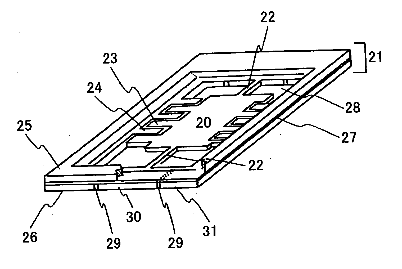
[0125]FIG. 9 is a diagram illustrating a first deflector mirror according to a third embodiment of the present invention. The deflector mirror of FIG. 9 includes a mirror substrate 20 and a substrate 21. Flexural rigidity is set for each point of the mirror substrate 20 by the method illustrated in the first or second embodiment. An external force exerted on the mirror substrate 20 is caused by an electrostatic force exerted between comb-teeth-like movable electrodes 23 formed on the free ends of the mirror substrate 20 and comb-teeth-like fixed electrodes 24 formed on the inner sides of the substrate 21 corresponding to the free ends of the mirror substrate 20. The substrate 21 includes a first Si member 25 and a second Si member 26 joined through a silicon oxide film (an insulating film) 27. An opening 28 is formed in the first Si member 25 by anisotropic etching. The mirror substrate 20 and a torsion rotary shaft 22 are formed in the second Si member 26 by a semiconductor process...


PUM


Abstract

A deflector mirror is disclosed that includes a mirror substrate configured to vibrate in a reciprocating manner on beams as a torsional rotary shaft so as to deflect a light beam emitted from a light source. The mirror substrate includes multiple regions in each of portions thereof extending from the torsional rotary shaft to respective ends of the mirror substrate, the regions being different in flexural rigidity.

Description

BACKGROUND OF THE INVENTION [0001] 1. Field of the Invention [0002] The present invention relates generally to micro-optical systems realized by micromachining technology, and more particularly to a deflector mirror of a type that causes a mirror substrate to vibrate in a reciprocating manner around torsion beams as a torsional rotary shaft, the torsion beams each having one end thereof supported. The present invention also relates to apparatuses such as optical scanning devices and image forming apparatuses to which the deflector mirror is applied. The present invention relates to a technique suitable for the writing unit of an image forming apparatus such as an electrophotographic printer or copier. [0003] 2. Description of the Related Art [0004] A deflector mirror in which a mirror substrate supported by two beams provided on a straight line is caused to vibrate in a reciprocating manner around the two beams serving as a torsional rotary shaft by the electrostatic attraction betw...

Claims


Application Information

Patent Timeline
IPC IPC(8): B41J27/00G02B26/08
CPCG02B26/0841
Inventor FUJII, MITSUMISATO, YUKITONAKAJIMA, TOMOHIROHAYASHI, YOSHINORIMOCHIZUKI, EIJISAITOH, TETSUROUSASAKI, KOHKI
Owner RICOH KK
Why Eureka
Try Eureka