
Microfabricated ultrasonic transducers with bias polarity beam profile control and method of operating the same

a microfabricated ultrasonic transducer and beam profile technology, applied in the field of ultrasonic transducers, can solve the problems of reducing the effective use of the device, affecting the operation efficiency of the device, and poor control of the slice thickness of traditional ultrasound transducers

Inactive Publication Date: 2006-08-08
SIEMENS MEDICAL SOLUTIONS USA INC
View PDF21 Cites 99 Cited by
  • Summary
  • Abstract
  • Description
  • Claims
  • Application Information

AI Technical Summary

Benefits of technology

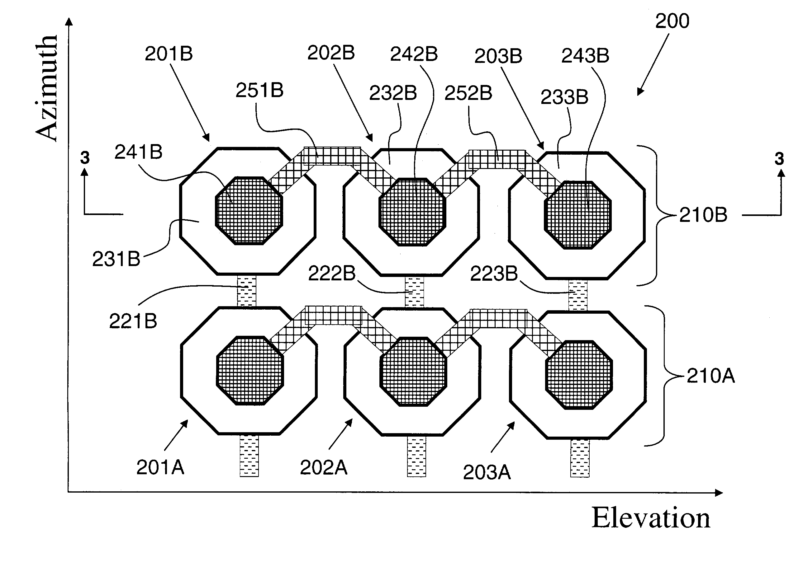
[0014]The present invention provides a cMUT that can be focused in the elevation direction by varying the sign of the applied bias in the elevation direction. In one aspect of the present invention, elevation focusing is achieved without the aid of a mechanical lens. The cMUT of the present invention provides enhanced multi-row focusing performance without the expense and complexity of the high-voltage switches required in multi-row probes and without the signal degradation that occurs when the RF signal passes through these lossy, high voltage switches. Additionally, the present invention provides a simple and effective means for controlling the aperture of a microfabricated ultrasonic transducer in both transmit and receive operation. The present invention also provides a means for steering the cMUT transmission beam in the elevation direction.
[0015]The present invention achieves these and other goals by providing a method for controlling the elevation slice thickness in both the near field and the far field of a cMUT's usable range. The near field improvement is obtained by reducing both the effective radiating and receiving aperture. In the far field, phase focusing is applied to reduce the slice thickness. In many applications of medical ultrasound, it is advantageous to split the displayed image into several “focal zones” that result from individual transmit firings. Combining these focal zones leads to a composite image more closely approximating a confocal system. With aperture control and phase focusing, the elevation focal length can be altered to match the azimuth focus in each focal zone of the image.
[0016]Both effects are achieved by alternating the polarity of the bias across the elevation aperture. This is achievable in a microfabricated transducer by splitting the common electrode, which is typically continuous, into several elevation electrodes and does not require additional coaxial connections to the transducer, since all of the control is exerted by bias polarity. Further, all of the bias lines to be switched are at RF ground, which eliminates the disadvantages of complexity and signal degradation when switches are in the path of the RF signals.

Problems solved by technology

Traditional ultrasound transducers have poor control of the slice thickness.
This divergent lens focusing creates volume averaging artifacts that obscure small cysts and other clinically relevant, yet small feature size, information.
Furthermore, practical physical lenses are often lossy, which further decreases their effective use, because they are made from materials whose speed of sound is slower than the speed of sound in a body.
However, by requiring delay means in both transmit and receive between “central” and “side” electrodes in elevation, in addition to azimuth delay means, this invention necessitates significant system and transducer complexity.
However, the practical complexity of dividing M azimuth channels into N segments in elevation, the N segments grouped into E apertures, is a material disadvantage to this type of design.
However, this approach negatively impacts at least one of efficiency, lateral resolution, or frame rate.
While this invention is known to those skilled in the art as resulting in ultrasound probes with improved slice thickness performance over conventional probes, the elevation aperture is problematic for low-frequency, relatively narrow-band signals such as those emanating from deep within the tissue.
Furthermore, fabrication of these curved surfaces is challenging and consequently expensive.
The Savord patent further teaches that elevation apodization can be achieved by varying the gain in the elevation direction with the bias rows; inherent in the Savord apodization teaching is the complexity of multiple bias sources each at different voltage amplitudes, which is not desirable in practical applications.

Method used


Image

  • Microfabricated ultrasonic transducers with bias polarity beam profile control and method of operating the same
  • Microfabricated ultrasonic transducers with bias polarity beam profile control and method of operating the same
  • Microfabricated ultrasonic transducers with bias polarity beam profile control and method of operating the same

Examples


Embodiment Construction

[0027]The present invention will now be described in detail with reference to the drawings, which are provided as illustrative examples of the invention so as to enable those skilled in the art to practice the invention. Notably, the figures and examples discussed below are not meant to limit the scope of the present invention. Moreover, where certain elements of the present invention can be partially or fully implemented using known components, only those portions of such known components that are necessary for an understanding of the present invention will be described, and detailed descriptions of other portions of such known components will be omitted so as not to obscure the invention. Further, the present invention encompasses present and future known equivalents to the known components that are, by way of illustration, referred to within this disclosure.

[0028]The present invention provides a capacitive microfabricated ultrasonic transducer (cMUT) with control of elevation pha...


PUM


Abstract

A capacitive microfabricated ultrasonic transducer with control of elevation phase through alternating bias polarity is disclosed. Such control of elevation phase results in simple ultrasonic probes with excellent slice thickness attributes. Furthermore, tight spatial variation of phase results in an effective way to achieve transmit aperture and apodization control. Further still, such capacitive microfabricated ultrasonic transducers can achieve elevation focus without the need of a lossy mechanical lens.

Description

FIELD OF THE INVENTION[0001]The present invention generally relates to the field of ultrasonic transducers. More specifically, the present invention relates to elevation beam profile control of capacitive microfabricated ultrasonic transducers.BACKGROUND OF THE INVENTION[0002]An acoustic transducer is an electronic device used to emit and receive sound waves. Ultrasonic transducers are acoustic transducers that operate at frequencies above 20 KHz, and more typically, in the 1–20 MHz range. Ultrasonic transducers are used in medical imaging, non-destructive evaluation, and other applications. The most common forms of ultrasonic transducers are piezoelectric transducers. Recently, a different type of ultrasonic transducer, the capacitive microfabricated ultrasonic transducer, has been described and fabricated. Such transducers are described by Haller et al. in U.S. Pat. No. 5,619,476 entitled “Electrostatic Ultrasonic Transducer,” issued Apr. 9, 1997. The Haller patent describes trans...

Claims


Application Information

Patent Timeline
IPC IPC(8): A61B8/14B06B1/02G01S15/89G10K11/34
CPCB06B1/0292G10K11/341G01S15/8925G01S7/52046
Inventor DAFT, CHRISTOPHER M. W.WAGNER, PAUL A.LADABAUM, IGAL
Owner SIEMENS MEDICAL SOLUTIONS USA INC
Learn More