Catheter assemblies and injection molding processes and equipment for making the same

a catheter and assembly technology, applied in the field of catheter assemblies, can solve the problems of time or cost savings for manufacturers, long, thin, tubular objects such as catheters have traditionally been very difficult to produce using such injection molding technologies, and difficulty, etc., to achieve rapid and inexpensive manufacturing, accurate tip geometry, and easy and comfortable insertion

Inactive Publication Date: 2005-02-10
BECTON DICKINSON & CO
View PDF4 Cites 189 Cited by
  • Summary
  • Abstract
  • Description
  • Claims
  • Application Information

AI Technical Summary

Benefits of technology

In the catheter assemblies of the invention, the hub portion of the catheter assembly is a generally tubular component used as an interface between the cannula portion and devices for introducing or withdrawing fluid from the body such as syringes. The hub portion includes a hub barrel, hub base, and a hub adapter. The hub barrel is the main tubular body of the catheter hub and includes a lumen for receiving a tip portion of a fluid withdrawal / introduction device such as a syringe or IV line, and for conveyance of fluid. The hub barrel is generally tapered internally and externally. The hub base protrudes from an end of the hub barrel in the form of a ridge. This ridge may further include flanges such as luer threads for locking the catheter assembly to an external device such as a syringe or an IV line in a secure, and often sealed, fashion. The flanges may also assist a user in grasping the hub barrel of the catheter assemblies of the invention.
The use of even flows of molten plastic makes it unnecessary to employ extra steps to protect the core pin against bending. Some traditional injection molding processes utilize an external mechanism, such as a hydraulically operated clamp, to tension a core pin or other protrusion to form a bore in the injection molded part. Such mechanisms add to the complexity of the molding apparatus and increase the cycle time of the injection molding process, thereby increasing the cost of the injection molded parts. The present invention avoids this requirement, thus avoiding cost and reducing production time requirements,
The cavity of the mold may be shaped such that the catheter assembly produced therein may have accurate tip geometry that promotes easier and more comfortable insertion of the catheter into a blood vessel. The catheter assembly may be rapidly and inexpensively manufactured by the injection molding process described above, without the need for separate attachment or tipping operations. Consequently, the catheter assembly and method of the present invention may contribute to the comfort, reliability, and cost effectiveness of medical care.

Problems solved by technology

The speed, efficiency, and consistency of these processes often results in time or cost savings to a manufacturer.
Long, thin, tubular objects such as catheters have traditionally been very difficult to produce using such injection molding technologies.
This difficulty arises for a number of reasons.
First, the extremely high pressures involved in injection molding processes generally render proposed processes unusable.
As a result, when flows of the highly-pressurized plastic are allowed to enter the cavity of the injection mold, any imbalance in the flows, regardless of how slight, may deflect the core pin used to produce the tubular lumen of the component from its proper position.
This often results in a damaged, and potentially unusable, product.
This results in multiple flows of molten plastic flowing into the mold.
Despite this, however, flow imbalances may still occur.
In many such cases these flow imbalances occur at least in part because the multiple flows may not enter the cavity in a simultaneous manner.
In addition, imbalanced flows may occur when the flows of plastic are not evenly distributed about the core pin.
Use of such systems and additional research have shown, however, that even in systems where the core pin is placed in high tension, imbalanced material flows may deflect the core pin, thus causing the part produced in the mold to have a number of undesirable characteristics.
In many cases, these qualities include poor molecular orientation, excessive production of flash, internal stresses, and the like.
In many cases, these flaws may be significant enough to impair the performance of the part or render it inoperative.
Often, these alternate manufacturing procedures reduce ability of the producer to vary the shape, size, and overall geometry of the parts to be produced.
As discussed above, such post-production processing and the use of supplementary parts may be disadvantageous because of increased material and labor costs which may be associated with them.

Method used


Image

  • Catheter assemblies and injection molding processes and equipment for making the same
  • Catheter assemblies and injection molding processes and equipment for making the same
  • Catheter assemblies and injection molding processes and equipment for making the same

Examples


Embodiment Construction

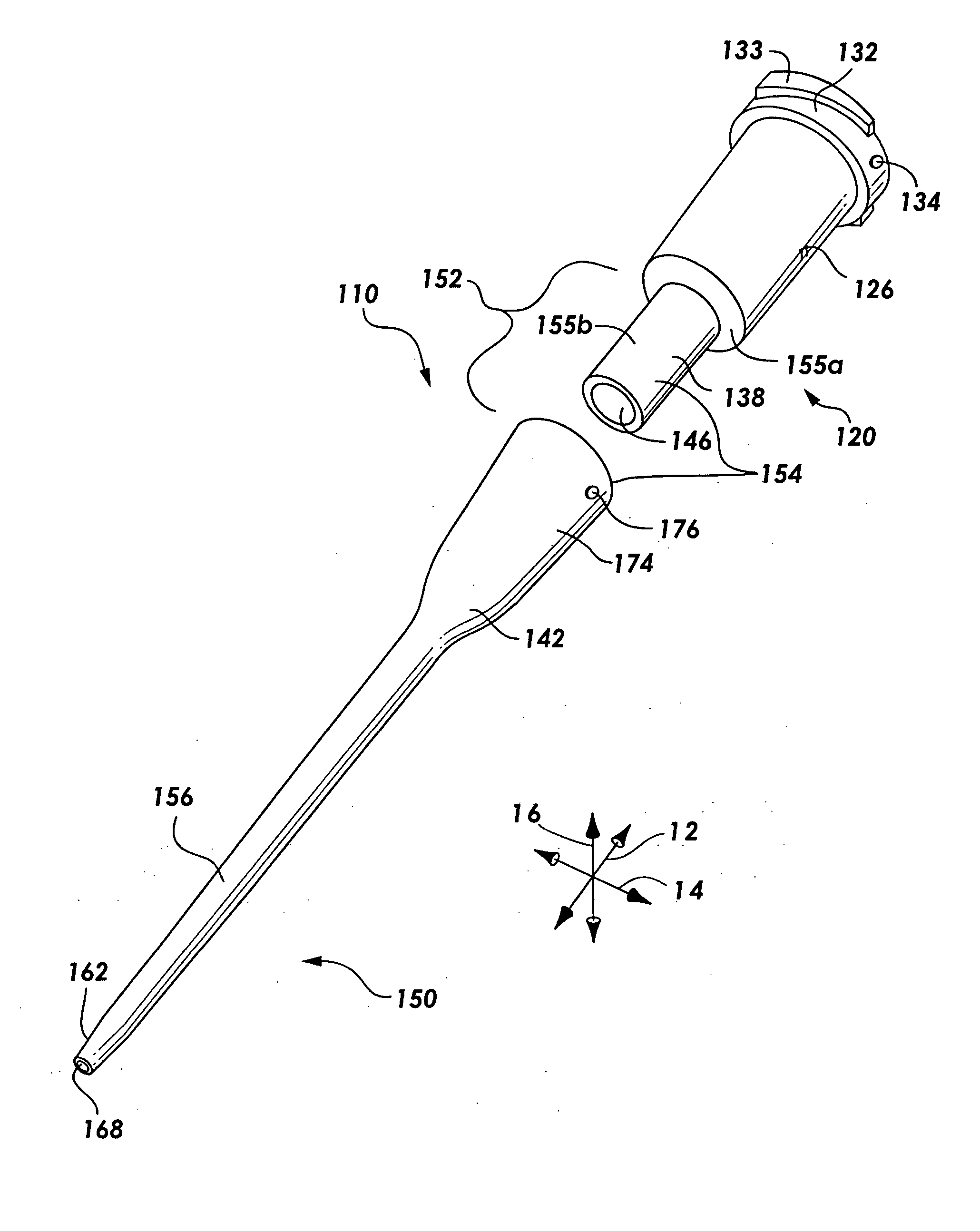
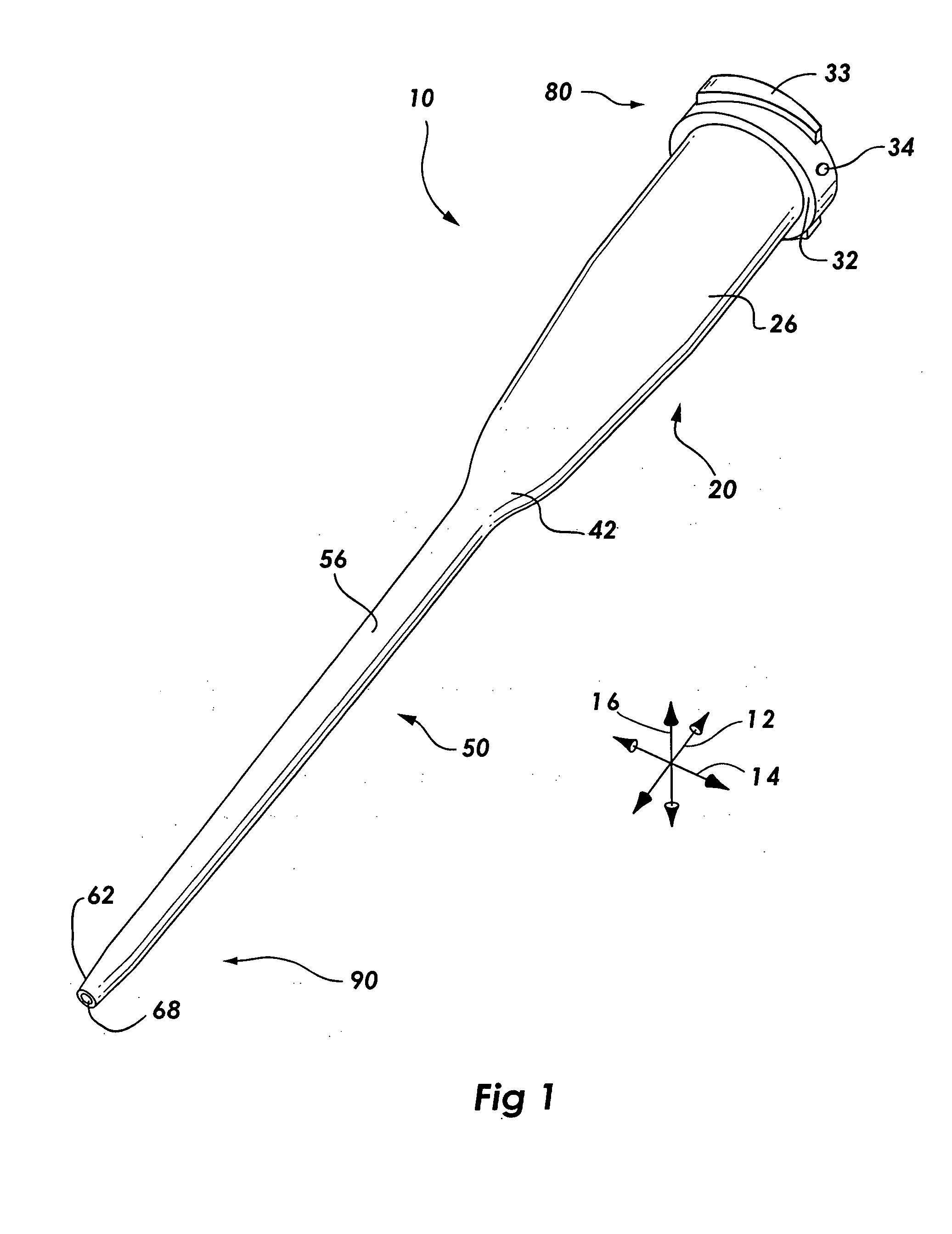
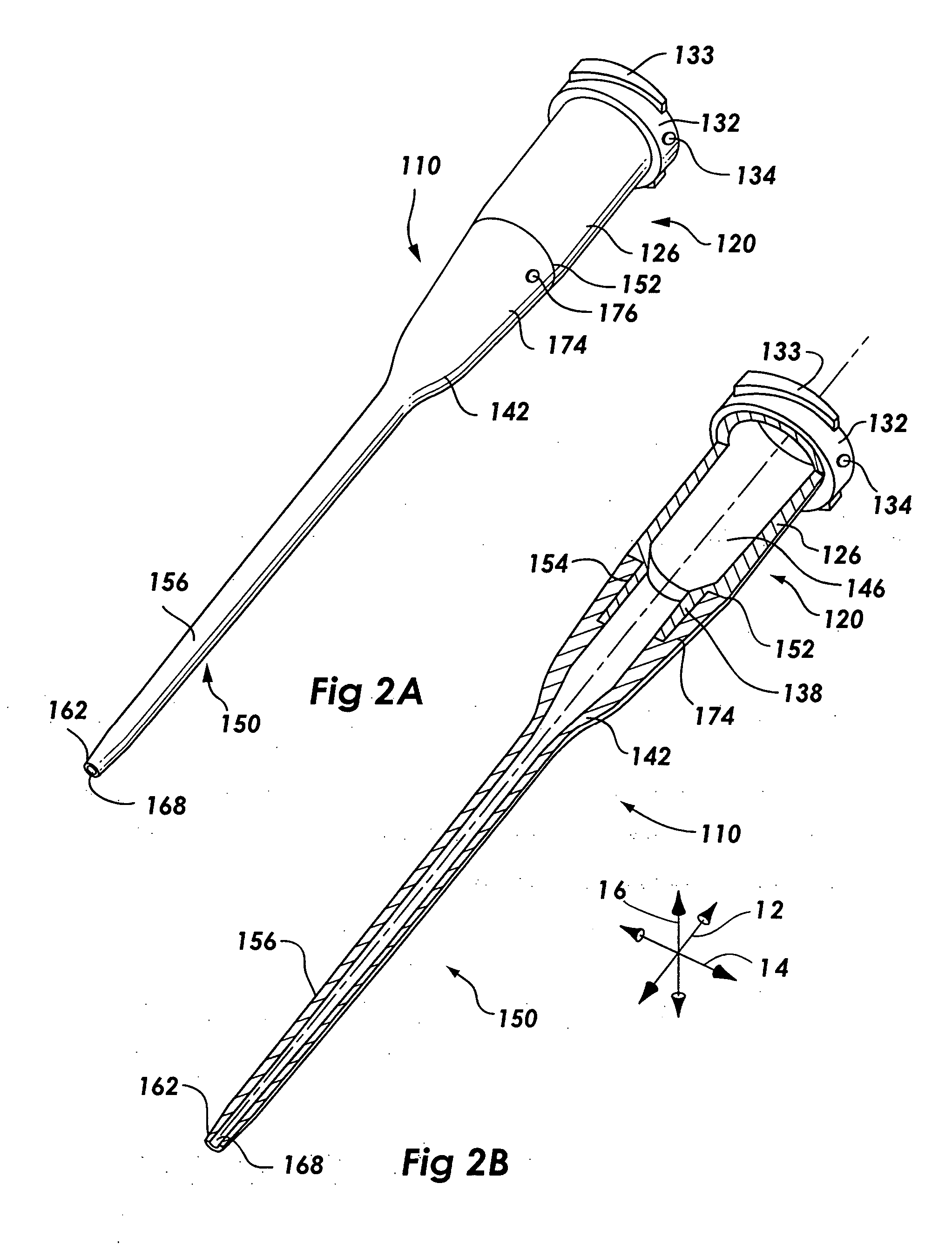
The presently preferred embodiments of the present invention will be best understood by reference to the drawings, wherein like parts are designated by like numerals throughout. It will be readily understood that the components of the present invention, as generally described and illustrated in the figures herein, could be arranged and designed in a wide variety of different configurations. Thus, the following more detailed description of the embodiments of the apparatus, system, and method of the present invention, as represented in FIGS. 1 through 16, is not intended to limit the scope of the invention, as claimed, but is merely representative of presently preferred embodiments of the invention.

The present invention includes advances in catheter design, material selection, and mold design which combine to enable production of a catheter assembly, including a catheter hub and a catheter tube, using injection-molding technologies. The invention further provides catheters which ma...


PUM

PropertyMeasurementUnit
lengthaaaaaaaaaa
molecular weightaaaaaaaaaa
rigidaaaaaaaaaa

Abstract

Various single-part catheter assemblies, multi-part integrated catheter assemblies, and methods and apparatus for making the same are disclosed. The single-part catheter assemblies include a catheter hub integrally formed with a catheter tube for insertion into the bloodstream of a patient. The multi-part integrated catheter assemblies include a catheter hub integrally formed to a catheter tube for insertion into the bloodstream of a patient. The catheter assemblies of the invention may be injection molded in a single step or in multiple steps by injecting flows of molten plastic into a cavity of molds provided herein such that the flows converge into an even distribution about the circumference of the sleeve. The mold may have a core pin designed to fit into the cavity. Through the use of the even distribution of flows, the core pin may be seated within the cavity in an untensioned manner. The catheter assemblies of the invention may be produced of a single material or of multiple materials.

Description

BACKGROUND OF THE INVENTION 1. Field of the Invention The present invention relates to medical systems and devices. More specifically, the present invention relates to catheter assemblies which include catheters and catheter adapters produced as a single part or produced as integrated assemblies of multiple parts. The invention further includes methods of injection molding and apparatus for producing such catheter assemblies from a single material and from multiple materials. 2. Description of Related Art In an age of medicine in which injectable pharmaceuticals are ubiquitous in patient treatment regimens, indwelling catheters are a critical tool used in hospitals daily. Many medical treatments are dependent on devices and methods which allow the introduction of fluids into the body of a patient. Advances in catheter-related technologies have allowed a larger number of medical procedures to be performed intravenously instead of surgically. Indeed, procedures such as angioplasty...

Claims


Application Information

Patent Timeline
Patent Type & Authority Applications(United States)
IPC IPC(8): A61M25/00A61M25/16B29C45/00B29C45/16B29C45/26
CPCA61M25/0009A61M25/0014B29C45/00B29L2031/7542B29C45/261B29C45/2708B29C45/16B29C45/0001B29C45/0003B29K2075/00
Inventor FENTRESS, JAMESO'CONNOR, SCOTT A.WHITE, SCOTT A.MONAHAN, LAWRENCE A.MARTIN, FRANK E.TINGEY, KEVIN G.GAWRELUK, CRAIG N.
Owner BECTON DICKINSON & CO
Why Eureka
Try Eureka