MEMS gyros with quadrature reducing springs

a technology of quadrature reduction and springs, applied in the direction of acceleration measurement using interia forces, turn-sensitive devices, instruments, etc., can solve the problems of reducing the bandwidth of rotation that can be detected, increasing the gain, and charging the amplifier to clip

Active Publication Date: 2013-09-24
ROSEMOUNT AEROSPACE
View PDF12 Cites 17 Cited by
  • Summary
  • Abstract
  • Description
  • Claims
  • Application Information

AI Technical Summary

Benefits of technology

[0019]In certain embodiments, the suspended drive mass and the intermediate suspended mass are separated by a plurality of trenches, which can have a substantially constant width. The spring element of each drive spring can have a width greater than that of the spring element of each anchor spring. The anchor springs can be predominantly curved and the drive springs can be predominantly straight. The mass of each spring element can be advantageously distributed substantially equally across the respective off-axis common radius of the first and second anchor points thereof to reduce off-axis sensitivities. It is also contemplated that the length of each spring element can be distributed substantially equally across the respective off-axis common radius.
[0021]The invention also provides a spring set configuration for a MEMS device wherein each spring has a spring element with a cross-section having an etch angle that is in line or oblique with respect to the z-axis. The springs can impart a characteristic quadrature error, or out of plane motion, to the suspended mass or masses due to variations in etch angle. It is contemplated that the quadrature error due to process variations in the etch angle of springs which are in line or oblique with respect to the z-axis can be reduced by a factor of about 5 times or greater compared with traditional spring set configurations having similar process variations in etch angle. It is also contemplated that the characteristic quadrature error or out of plane motion can be substantially insensitive to process induced etch angle variation in the spring elements.

Problems solved by technology

But this increased gain comes at a cost in the form of decreased bandwidth of rotation that can be detected.
When an unwanted quadrature signal is too large, it can cause the charge amplifier to clip and any information of the desired rate signal is clipped along with it.
The quadrature error mitigation circuit is limited by the available voltage.
It is not uncommon for quadrature error to be so large that it cannot be corrected with a quadrature error mitigation circuit.
Larger compensation voltages may result in unacceptable noise levels in the device.
Minimizing unwanted quadrature by electrical means can make the microstructure useable, but high level performance characteristics such as Allan variance and temperature sensitivity may be compromised since they have been correlated to compensation voltage levels, probably due to the microstructure moving out of plane.
A primary cause of quadrature error is the etch angle variation in the microstructure components, and particularly in the springs.

Method used


Image

  • MEMS gyros with quadrature reducing springs
  • MEMS gyros with quadrature reducing springs
  • MEMS gyros with quadrature reducing springs

Examples


Embodiment Construction

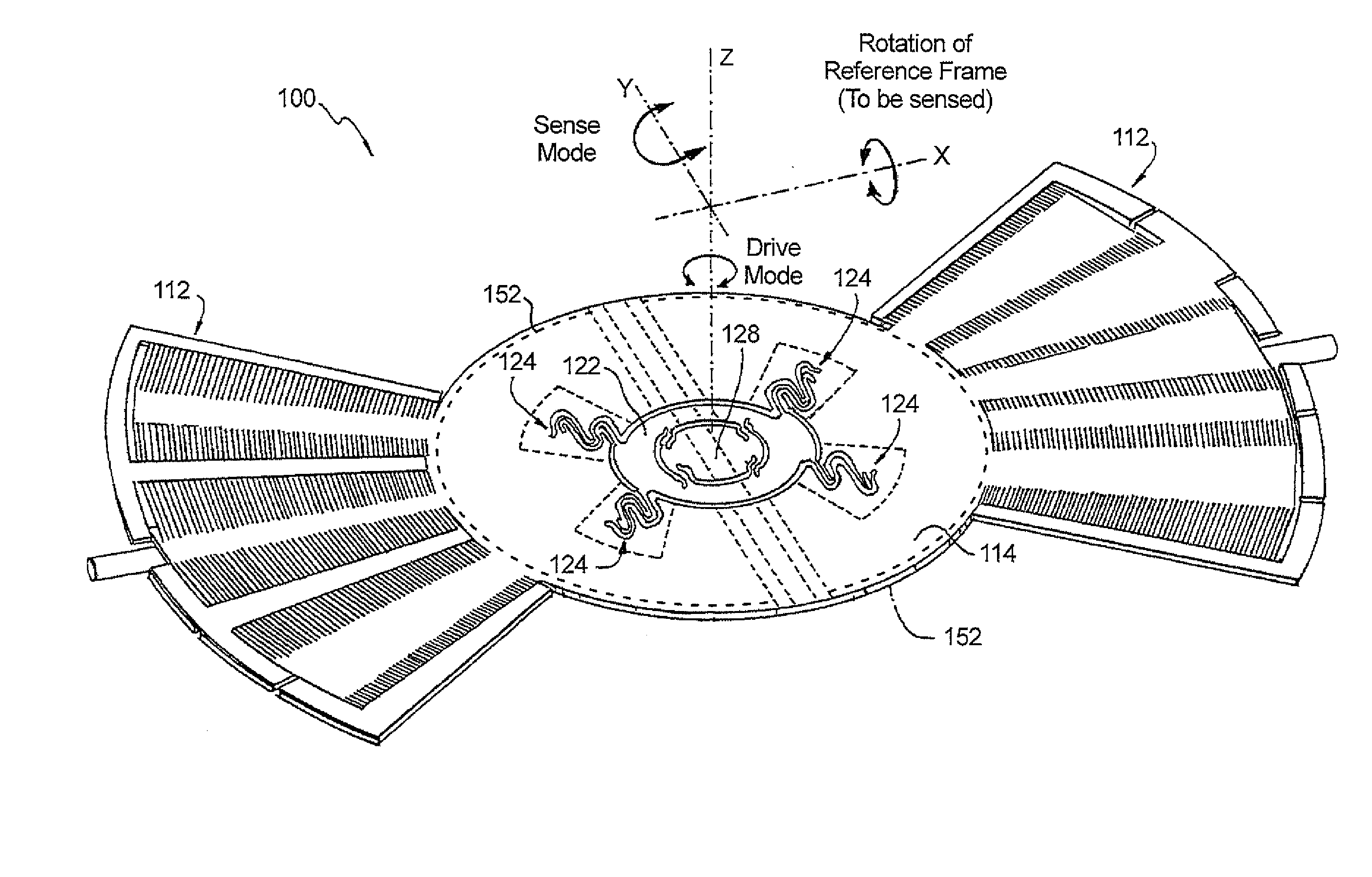
[0039]Reference will now be made to the drawings wherein like reference numerals identify similar structural features or aspects of the subject invention. For purposes of explanation and illustration, and not limitation, a partial view of an exemplary embodiment of a spring set configuration used on a MEMS gyro in accordance with the invention is shown in FIG. 2 and is designated generally by reference character 100. Other embodiments of spring set configurations used on MEMS gyros in accordance with the invention, or aspects thereof, are provided in FIGS. 3-13, as will be described. The systems and methods of the invention can be used reduce quadrature error in MEMS devices, and more particularly in MEMS gyros.

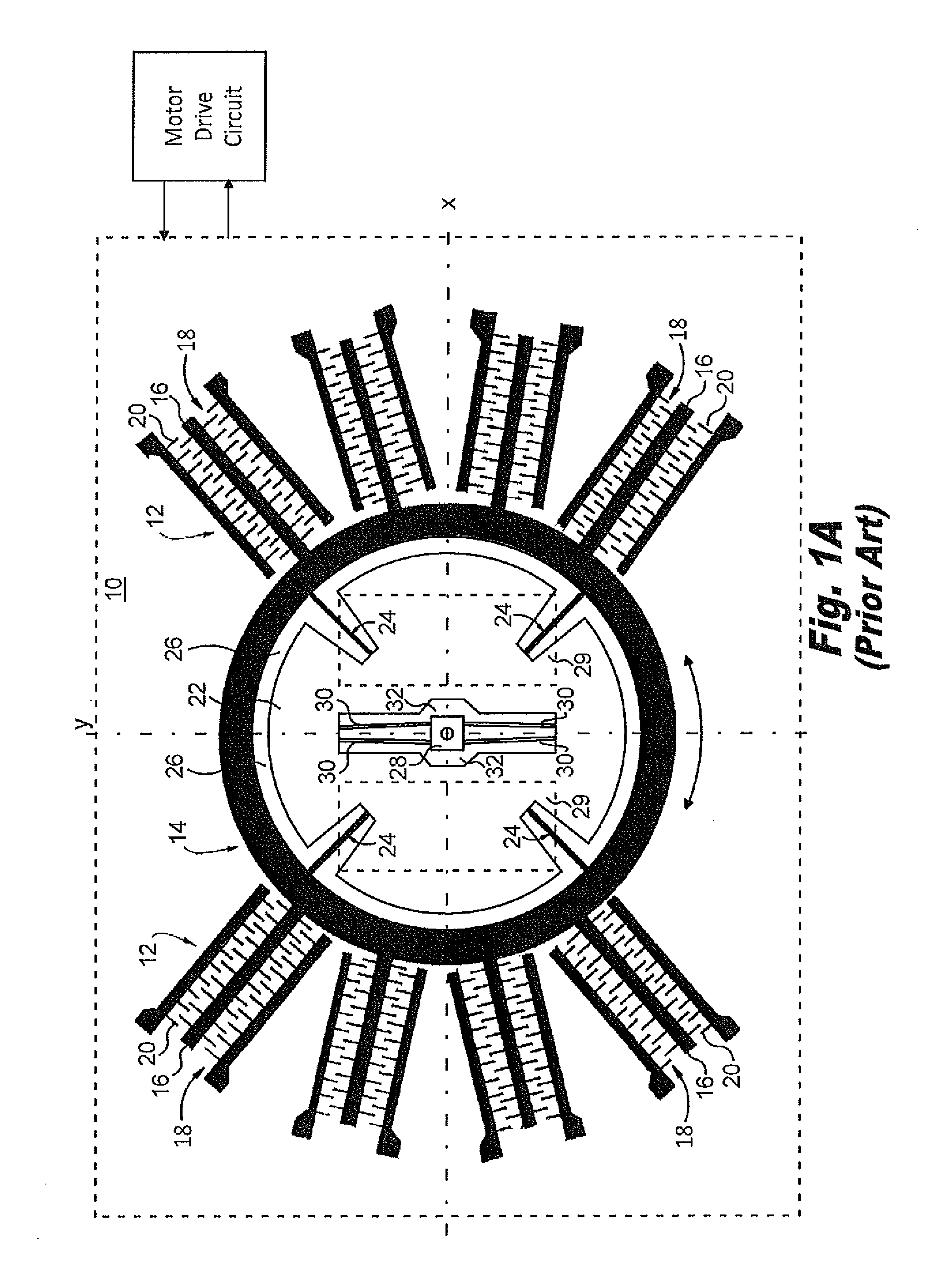
[0040]With reference to FIG. 1A, a portion of a prior art MEMS gyro 10 is shown in plan view. MEMS gyro 10 includes an opposed pair of comb drives 12. A drive mass 14 includes driven portions 16 that form part of comb drives 12, with intermeshing portions 18 formed between st...


PUM


Abstract

Spring set configurations that include an advantageous combination of spring geometries are disclosed. Spring elements having curved and straight sections, orientation of spring element anchor points with respect to the common radius, orientation of spring element segments with respect to a specific axis, balance of the length of spring elements about the common radius, and mass balance about the common radius can be used to mitigate unwanted out of plane motion. The spring set provides planar motion while reducing undesired out of plane motion making MEMS devices substantially insensitive to the process-induced etch angle variations of the spring elements. The spring set can be used in a MEMS gyro device which maintains the desired resonant modes and consistently low quadrature error even with process variations in manufacturing causing undesirable etch angles.

Description

BACKGROUND OF THE INVENTION[0001]1. Field of the Invention[0002]The present invention relates to spring set configurations for microelectromechanical systems (MEMS) devices, and more particularly to spring set configurations for MEMS gyros.[0003]2. Description of Related Art[0004]A variety of gyroscope devices are known for providing navigational guidance such as in aerospace applications. Microelectromechanical systems gyroscopes (hereinafter MEMS gyros) are known for their compact size and relatively low cost of manufacture. In addition to aerospace applications, the small size and low cost of MEMS gyros lends them well to a variety of other applications including motion sensing for image stabilization and input devices, for example.[0005]Gyros operate by moving a mass. When the mass is located in a rotating reference frame, for example, it will be subjected to a Coriolis force calculated by the formula:Fc=2mv×Ω, where Fc is the Coriolis force, m is the mass of the moving body, v ...

Claims


Application Information

Patent Timeline
Patent Type & Authority Patents(United States)
IPC IPC(8): G01C19/56
CPCG01C19/56G01C19/5712
Inventor POTASEK, DAVID PATRICKCHILDRESS, MARCUS ALLENCHRISTENSON, JOHN CARL
Owner ROSEMOUNT AEROSPACE
Why Eureka
Try Eureka