Check patentability & draft patents in minutes with Patsnap Eureka AI!

Disk loading device having positioning and detection levers that move entirely outside an outermost circumference of an area occupied by a disk mounted therein

a technology of positioning and detection levers and disk loading devices, which is applied in the direction of data recording, instrumentation, carrier constructional parts disposition, etc., can solve the problems of difficult to reduce the thickness (a dimension perpendicular to the mounted disk) of the disk loading device, and the upper face of the mounted disk cannot be seen from outside the disk loading device. to achieve the effect of slimming down the disk loading devi

Inactive Publication Date: 2011-02-22
SIEMENS AG +1
View PDF13 Cites 0 Cited by
  • Summary
  • Abstract
  • Description
  • Claims
  • Application Information

AI Technical Summary

Benefits of technology

[0015]According to this invention, components of a disk positioning mechanism including the third and fourth detecting levers and the third and fourth positioning levers for positioning the large-diameter disk and the small-diameter disk in the disk mounted position are mounted outside the large-diameter disk-mounted-area. Therefore, the components of the disk positioning mechanism do not exist above the upper face of the disk in a state in which mounting of the disk has been completed. Therefore, it is possible to slim down the disk loading device.
[0016]According to this invention, the detecting lever, the trigger lever, and the left and right centering levers for positioning the large-diameter disk and the small-diameter disk are mounted outside the large-diameter disk-mounted-area. Therefore, the respective levers do not exist above the upper face of the disk when the large-diameter or small-diameter disk is mounted in the disk mounted position. As a result, it is possible to see the upper face of the mounted large-diameter or small-diameter disk from outside the disk loading device. Thus, it is possible to visually check presence or absence of the disk, the upper face of the disk (e.g., the label face), and a rotating state of the disk. Because the respective levers do not exist above the upper face of the disk, it is possible to slim down the disk loading device.

Problems solved by technology

Therefore, it is impossible to see the upper face of the mounted disk from outside the disk loading device.
Moreover, a mechanism parts are provided above the upper face of the disk and therefore it is difficult to reduce a thickness (a dimension in a direction perpendicular to a face of the mounted disk) of the disk loading device.

Method used


Image

  • Disk loading device having positioning and detection levers that move entirely outside an outermost circumference of an area occupied by a disk mounted therein
  • Disk loading device having positioning and detection levers that move entirely outside an outermost circumference of an area occupied by a disk mounted therein
  • Disk loading device having positioning and detection levers that move entirely outside an outermost circumference of an area occupied by a disk mounted therein

Examples


first embodiment

[0056]A disk loading device of a first embodiment of the present invention will be described with reference to FIGS. 1 to 18.

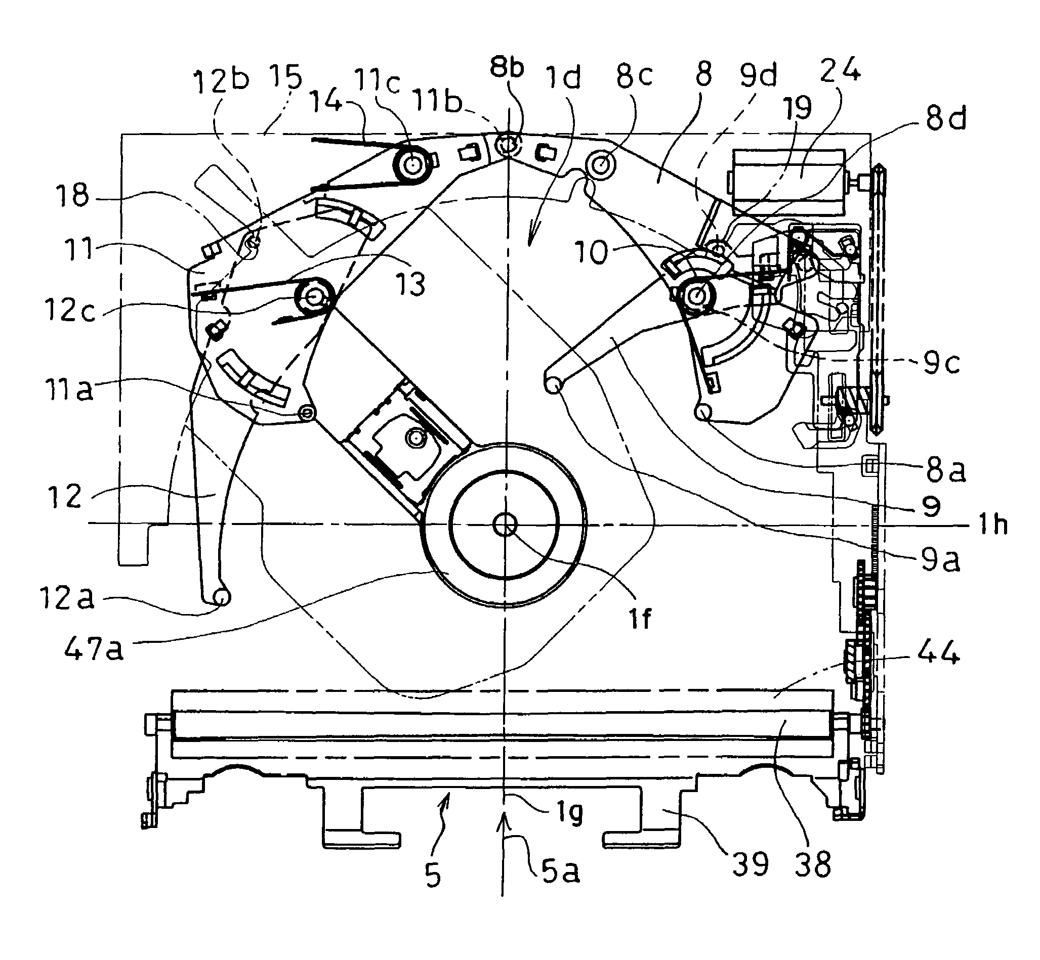
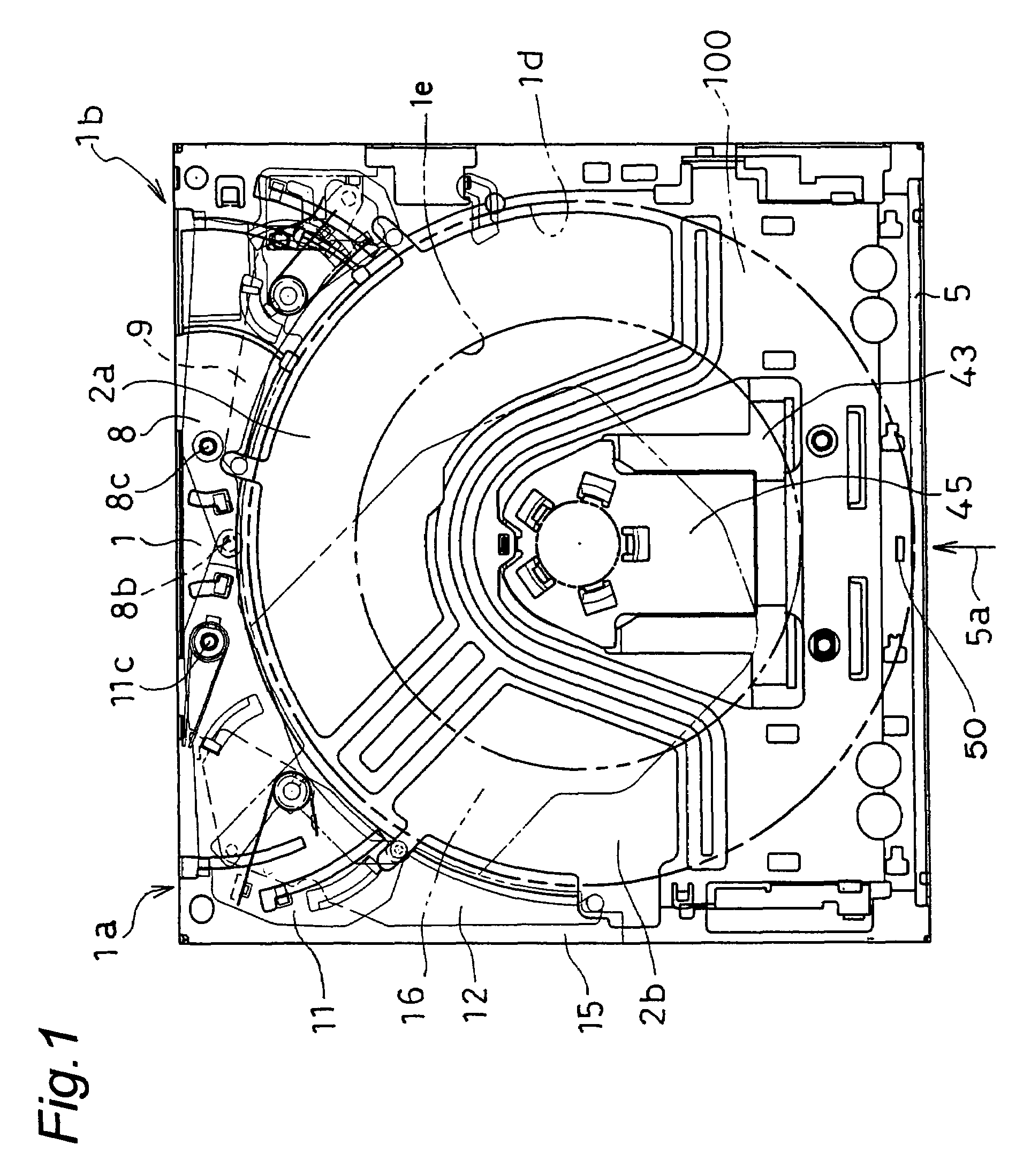
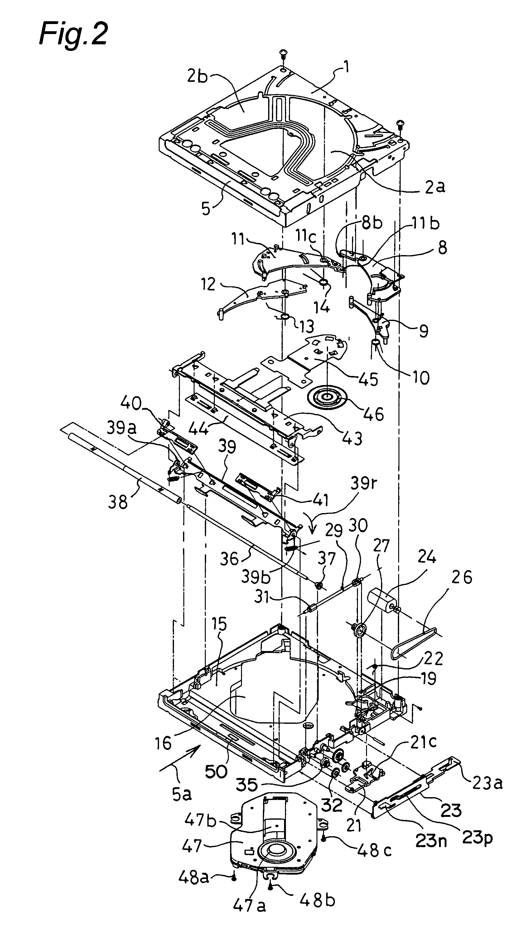
[0057]FIG. 1 is a top view of the disk loading device of the first embodiment of the present invention and FIG. 2 is an exploded perspective view of the same. FIGS. 3 to 6 are top views showing operation when a disk of standardized diameter of 12 cm (hereafter referred to as a large-diameter disk 100) is mounted in the disk loading device. FIGS. 7A to 9A are partial top views showing movement of a trigger lever when the large-diameter disk 100 is mounted. FIGS. 10 to 13 are top views of the disk loading device and showing operation when a disk of standardized diameter of 8 cm (hereafter referred to as a small-diameter disk 120) is mounted. FIGS. 14A to 15A are partial top views showing operation of the trigger lever 9 when the small-diameter disk 120 is mounted. FIGS. 16 to 18 are right side views of FIG. 13.

[0058]In FIGS. 1 and 2, the disk loading device of t...

second embodiment

[0097]Next, a disk loading device of a second embodiment of the present invention will be described with reference to FIGS. 19 to 28.

[0098]FIG. 19 is an exploded perspective view of the disk loading device of the second embodiment and FIG. 20 is a top view showing a standby state before insertion of a disk. FIG. 21 is a top view showing operation during insertion of the large-diameter disk 100 of standardized diameter of 12 cm into the disk loading device. FIG. 22 is a partial top view showing movement of a trigger lever 109 during insertion of the large-diameter disk 100. FIG. 23 is a top view showing a state of the disk loading device after completion of mounting of the large-diameter disk 100. FIG. 24 and FIGS. 26 to 28 are top views of the disk loading device and showing operation when the small-diameter disk 120 of standardized diameter of 8 cm is inserted. FIG. 25 is a partial top view showing operation of the trigger lever 109 during mounting of the small-diameter disk 120.

[0...


PUM

PropertyMeasurementUnit
diameteraaaaaaaaaa
diameteraaaaaaaaaa
diameteraaaaaaaaaa

Abstract

Two positioning levers for positioning a disk and two detecting levers are provided outside an area in a disk loading device where the disk is to be mounted. A large-diameter disk is positioned when both of the two detecting levers come in contact with the disk. At the time of insertion of a small-diameter disk when one of the detecting levers comes in contact with the disk, the two positioning levers do not move and the small-diameter disk is positioned.

Description

BACKGROUND OF THE INVENTION[0001]The present invention relates to a disk loading device (disk drive device) for inserting a disk-shaped recording medium into the device and mounting the recording medium in a disk mounted position.[0002]A disk loading device is used in many fields as a device for inserting a disk such as a CD that is an optical disk for sound, a DVD that is an optical disk for image, and various optical disks for computers into the device and mounting the disk in a disk mounted position for optically recording and reproducing data on the disk. As an optical disk not housed in a case and used alone out of the above-described optical disks, two kinds of disks, i.e., a disk (large-diameter disk) of standardized diameter of 12 cm and a disk (small-diameter disk) of standardized diameter of 8 cm are used widely. Therefore, as the disk loading device, a dual-purpose disk loading device for driving both the large-diameter disk and the small-diameter disk is in the actual us...

Claims


Application Information

Patent Timeline
Patent Type & Authority Patents(United States)
IPC IPC(8): G11B17/04G11B33/12
CPCG11B17/0404G11B17/0515
Inventor ISHIKAWA, KAZUOYOSHIDA, NORIKATSUMORIOKA, YUKIOYAMAZAKI, TAKUTO
Owner SIEMENS AG
Features
  • R&D
  • Intellectual Property
  • Life Sciences
  • Materials
  • Tech Scout
  • Unparalleled Data Quality
  • Higher Quality Content
  • 60% Fewer Hallucinations
Learn More