LED illumination device

a technology of illumination device and led light, which is applied in the direction of semiconductor devices for light sources, lighting and heating apparatus, lighting support devices, etc., can solve the problem that the illumination device cannot obtain the desired illumination area

Inactive Publication Date: 2011-04-05
HON HAI PRECISION IND CO LTD
View PDF8 Cites 79 Cited by
  • Summary
  • Abstract
  • Description
  • Claims
  • Application Information

AI Technical Summary

Benefits of technology

[0006]For an LED, about eighty percents of the power consumed thereby is converted into heat. Therefore, a heat dissipation device is necessary for timely and adequately removing the heat generated by the LED. Generally, the illumination device includes a plurality of LEDs and the LEDs are arranged on a flat surface whereby an illumination area of the LEDs is limited. Thus, the illumination device cannot obtain a desired illumination area.

Problems solved by technology

Thus, the illumination device cannot obtain a desired illumination area.

Method used


Image

  • LED illumination device
  • LED illumination device
  • LED illumination device

Examples


Embodiment Construction

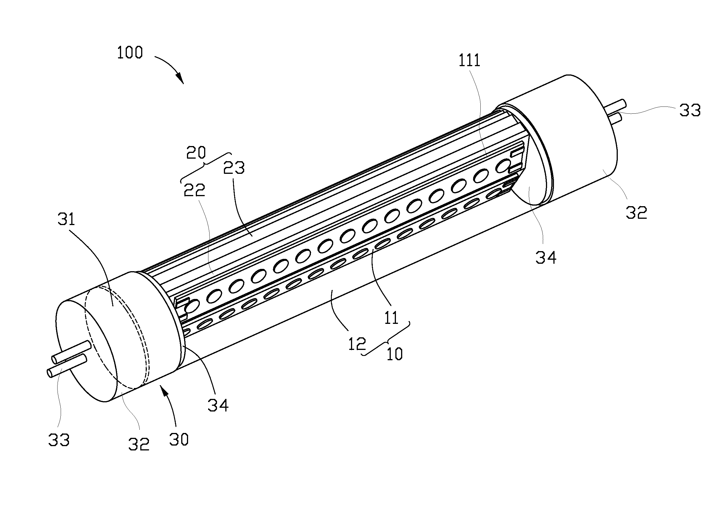
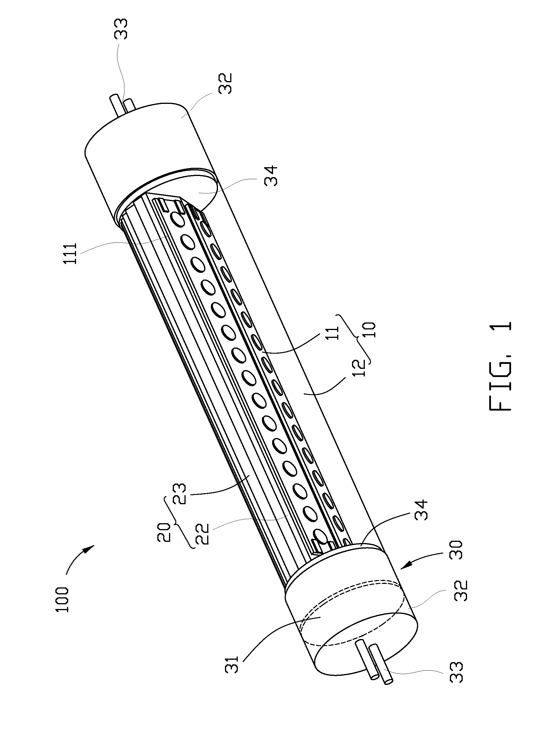
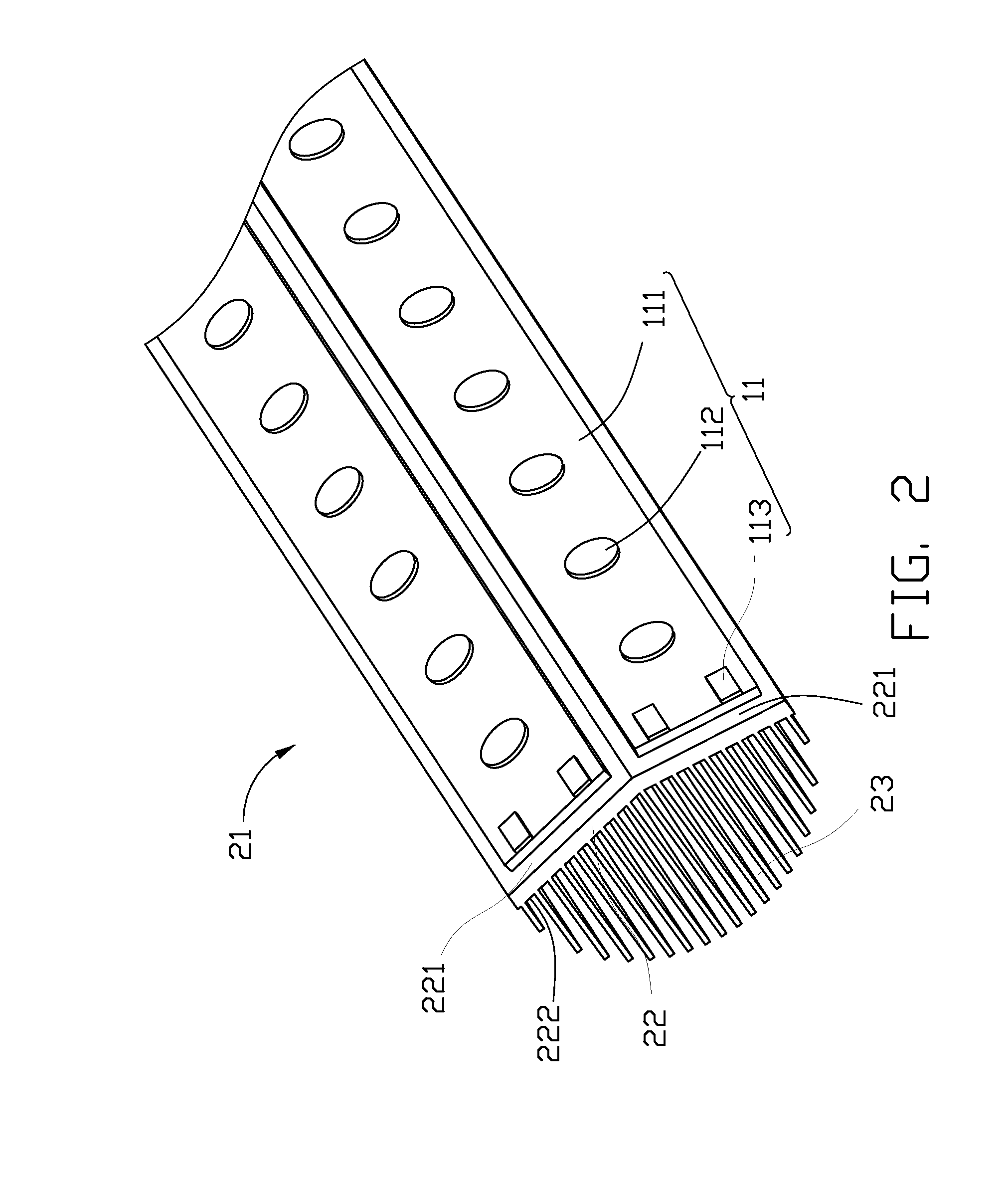
[0018]Referring to FIGS. 1 and 2, an LED illumination device 100 according to an exemplary embodiment includes a light-emitting module 10, a heat sink 20 arranged above the light-emitting module 10, and an electrical module 30 electrically connected with the light-emitting module 10.

[0019]The heat sink 20 includes an elongated metal base 22 and a plurality of metal fins 23 extending from the base 22. The base 22 is substantially V-shaped, and has a convex surface 221 and an opposite concave surface 222. Each of the convex surface 221 and the concave surface 222 is constructed by two intersecting flat surface portions. The fins 23 extend vertically upwardly from the concave surface 222 of the base 22, and are arranged symmetric to a joint of the two surface portions of the concave surface 222. A height of the fins 23 decreases from the joint of the concave surface 222 towards two opposite lateral sides of the base 22. Upper free ends of the fins 23 cooperatively form an imaginary con...


PUM


Abstract

An LED illumination device includes a light source and a heat sink. The heat sink includes an elongated base and a plurality of fins extending from the base. The base has a heat-absorbing surface and an opposite heat-spreading surface. The fins extend upwardly from the heat-spreading surface. The light source is attached to the heat-absorbing surface, whereby heat generated by the light source is removed by the heat sink. The heat-absorbing surface is one of a convex surface and a concave surface, whereby light emitted from the light source is diverged or converged towards objects.

Description

CROSS-REFERENCE TO RELATED APPLICATION[0001]This application is related to a co-pending U.S. patent application Ser. No. 12 / 423,020 filed on Apr. 14, 2009 and entitled “LED ILLUMINATION DEVICE AND LIGHT ENGINE THEREOF”. The co-pending U.S. patent application is assigned to the same assignee as the instant application. The disclosure of the above-identified application is incorporated herein by reference.BACKGROUND[0002]1. Technical Field[0003]The present disclosure relates to an LED illumination device.[0004]2. Description of Related Art[0005]In recent years, LEDs are preferred for use in illumination devices rather than CCFLs (cold cathode fluorescent lamps) due to their excellent properties, including high brightness, long lifespan, wide color range, and etc.[0006]For an LED, about eighty percents of the power consumed thereby is converted into heat. Therefore, a heat dissipation device is necessary for timely and adequately removing the heat generated by the LED. Generally, the i...

Claims


Application Information

Patent Timeline
Patent Type & Authority Patents(United States)
IPC IPC(8): F21V7/20F21V29/505
CPCF21K9/00F21K9/17F21V29/004F21V29/89F21V29/75F21V29/76F21Y2101/02F21Y2111/005F21Y2103/003F21K9/27F21Y2103/10F21Y2115/10F21Y2107/30
Inventor LIU, TAY-JIAN
Owner HON HAI PRECISION IND CO LTD
Why Eureka
Try Eureka