Overcurrent protection circuit and method of protecting power supply circuit

a protection circuit and power supply technology, applied in emergency protection arrangements, emergency protection arrangements for limiting excess voltage/current, and arrangements responsive to excess current, etc., can solve problems such as high possibility of causing an overcurrent, long turn-on time of output transistor b>141/b>, and high operation difficulty

Active Publication Date: 2010-12-02
SEMICON COMPONENTS IND LLC
View PDF20 Cites 9 Cited by
  • Summary
  • Abstract
  • Description
  • Claims
  • Application Information

AI Technical Summary

Benefits of technology

[0016]The preferred embodiments of the present invention have been developed in view of the above-mentioned and / or other problems in the related art. The preferred embodiments of the present invention can significantly improve upon existing methods and / or apparatuses.

Problems solved by technology

Therefore, when PWM control is performed based on the large error, the turn-on time of the output transistor 141 becomes very long.
As a result, the possibility of causing an overcurrent is high since the output is virtually grounded to a large-capacity capacitor 122.
However, when the overcurrent detection circuit 148 recognizes as an overcurrent to turn off the output transistor 141, the power supply circuit 100 may causes a problem in operation.
However, if the output transistor 141 returns to an on-state immediately after the turn-off state, removal of heat generated in a system in which the power supply circuit 100 is mounted becomes sometimes insufficient.

Method used


Image

  • Overcurrent protection circuit and method of protecting power supply circuit
  • Overcurrent protection circuit and method of protecting power supply circuit
  • Overcurrent protection circuit and method of protecting power supply circuit

Examples


Embodiment Construction

[0035]In the following paragraphs, some preferred embodiments of the invention will be described by way of example and not limitation. It should be understood based on this disclosure that various other modifications can be made by those in the art based on these illustrated embodiments.

[0036]Hereinafter, a preferable embodiment of the present invention will be explained with reference to the attached drawings. In the following explanation, although the entire structure of a power supply circuit in which an overcurrent protection circuit is mounted will not be explained, an overcurrent protection circuit can be mounted in, for example, the power supply circuit 100 having a soft-start function as shown in FIG. 4.

[0037]The structure of an overcurrent protection circuit according to the present invention will be detailed as follows.

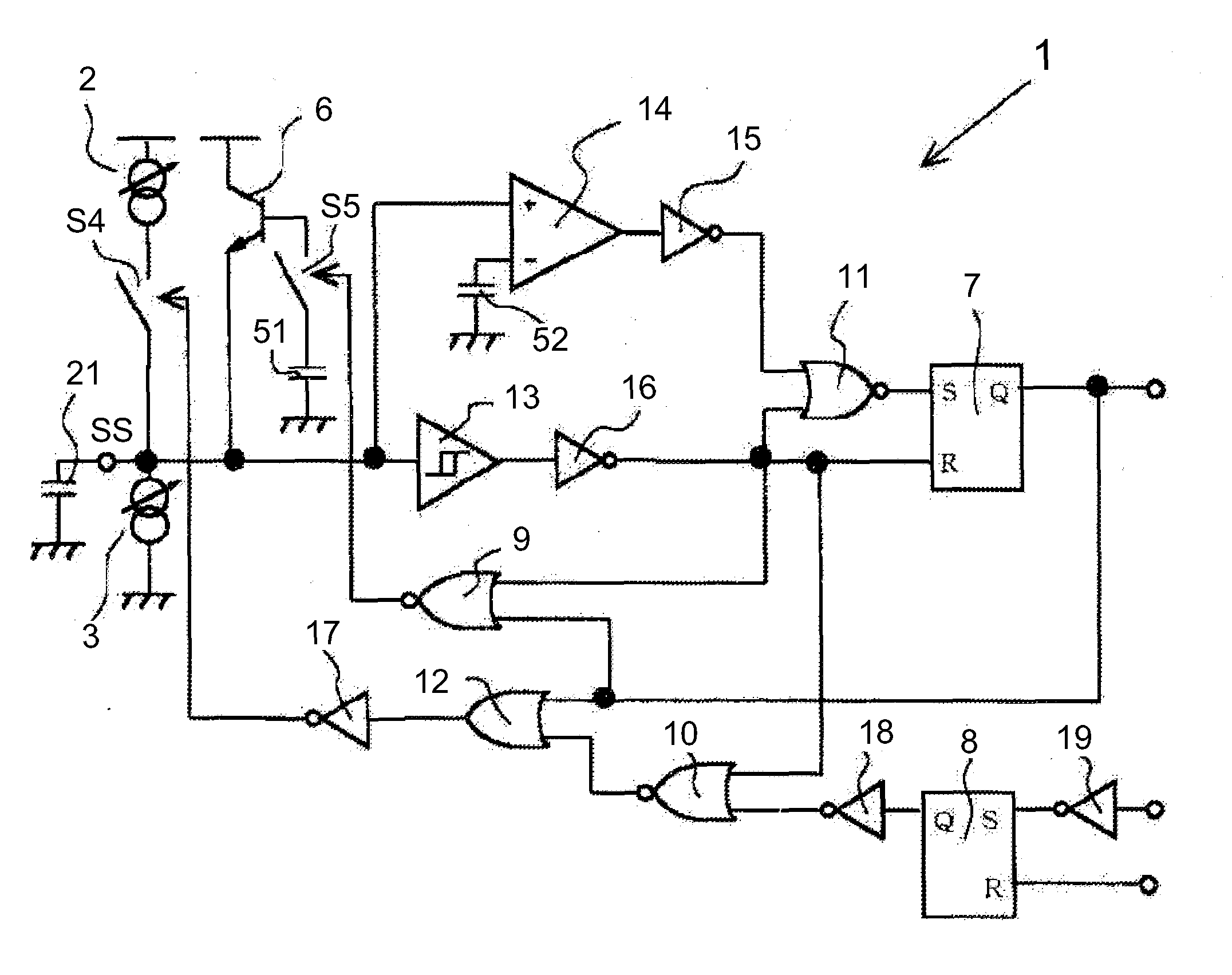
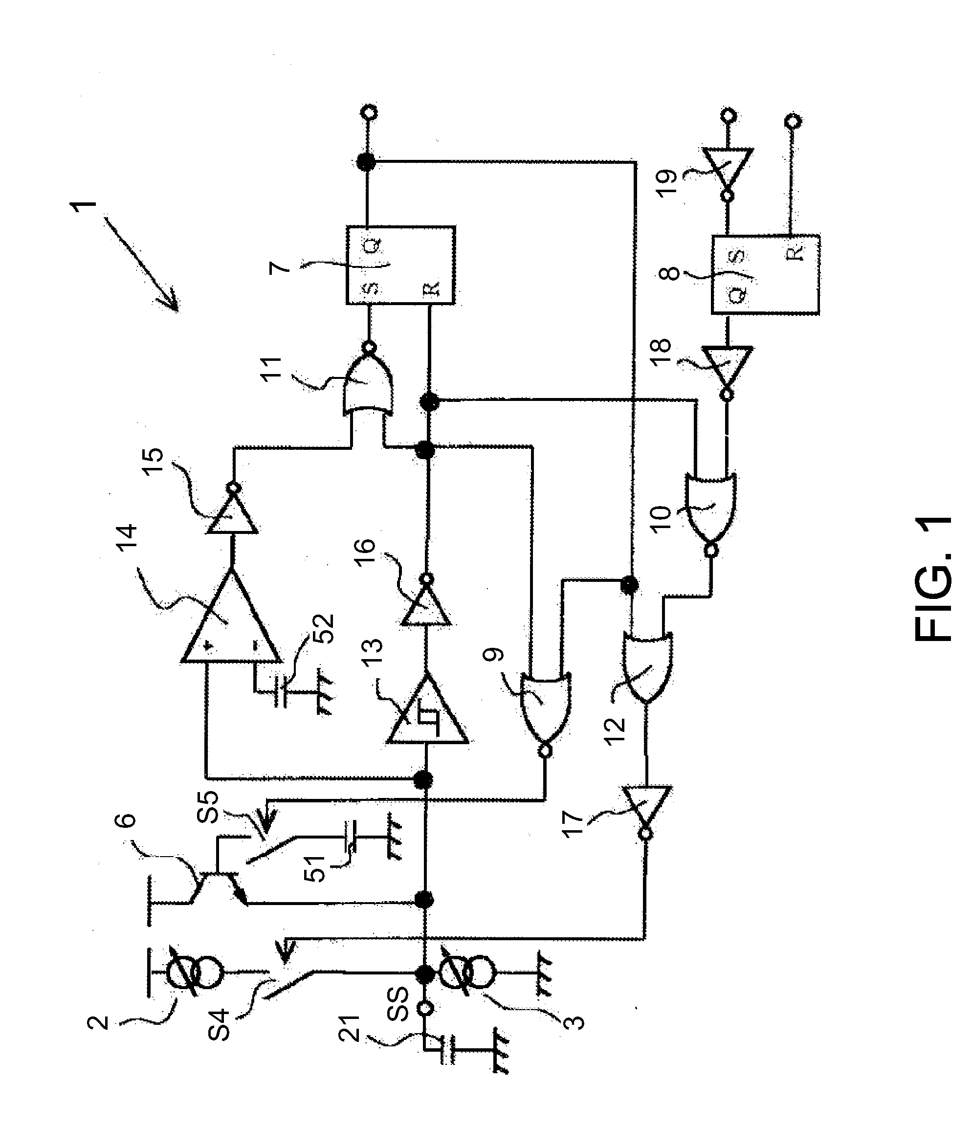
[0038]FIG. 1 is a circuit diagram showing an overcurrent protection circuit 1. This overcurrent protection circuit 1 includes current sources 2 and 3, switc...


PUM


Abstract

In some embodiments, an overcurrent protection circuit is configured to operate in accordance with operation modes including a first operation mode in which when the power supply circuit is activated, the capacitor is charged until the terminal voltage reaches a first voltage, a second operation mode in which depending on a time period in which a current flowing through an output transistor of the power supply circuit exceeds a predetermined value, the capacitor is charged so that the terminal voltage increases from the first voltage toward a second voltage, and the power supply circuit is shut down when the terminal voltage reaches the second voltage, and a third operation mode in which when the power supply circuit is shut down, the capacitor is discharged until the terminal voltage reaches a third voltage, and the shutdown of the power supply circuit is released when the terminal voltage reaches the third voltage.

Description

[0001]This application claims priority under 35 U.S.C. §119 to Japanese Patent Application No. 2009-129974 filed on May 29, 2009, the entire disclosure of which is incorporated herein by reference in its entirety.BACKGROUND OF THE INVENTION[0002]1. Field of the Invention[0003]The present invention relates to an overcurrent protection circuit for, e.g., preventing breakage of a power supply circuit due to an overcurrent or excess current, and also relates to a method of protecting a power supply circuit from an overcurrent flowing through an output transistor of the power supply circuit.[0004]2. Description of the Related Art[0005]The following description sets forth the inventor's knowledge of related art and problems therein and should not be construed as an admission of knowledge in the prior art.[0006]Currently, a power supply circuit is used in various electric equipments. In general, a power supply circuit is equipped with various protection functions for preventing breakage of...

Claims


Application Information

Patent Timeline
Patent Type & Authority Applications(United States)
IPC IPC(8): H02H9/02
CPCH02H3/093H02H9/001
Inventor UEDA, YASUYUKI
Owner SEMICON COMPONENTS IND LLC
Why Eureka
Try Eureka