Lighting device

a technology of light source and heat conductivity, which is applied in the direction of semiconductor devices for light sources, light and heating apparatus, point-like light sources, etc., can solve the problems of negative transportation effect and increase the weight of the device, and achieve the effect of higher heat conductivity and higher heat conductivity

Inactive Publication Date: 2010-02-25
NEC LIGHTING
View PDF2 Cites 8 Cited by
  • Summary
  • Abstract
  • Description
  • Claims
  • Application Information

AI Technical Summary

Benefits of technology

[0023]According to the present invention, heat generated from the light emitting unit is transferred to the heat conduction member from the heat transfer surface in the direction intersecting with the second direction having the higher heat conductivity. Namely, in the present invention, because the heat is transferred in the direction having the higher heat conductivity, the heat can be transferred in the second direction while suppressing an effect of the first heat conductivity lower than the second heat conductivity. Consequently, the present invention can sufficiently utilize heat diffusion characteristics of the heat conduction member having an anisotropic heat conductivity.

Problems solved by technology

However, the increased thickness of the body of a lighting device causes an increase in weight, resulting in a negative effect on transportation.
Further, such increased weight may exceed an allowable weight value of a rectangular ceiling rosette, 5 [Kg], that is directly installed on a ceiling when the lighting device is an appliance for household use.

Method used


Image

  • Lighting device
  • Lighting device
  • Lighting device

Examples


first exemplary embodiment

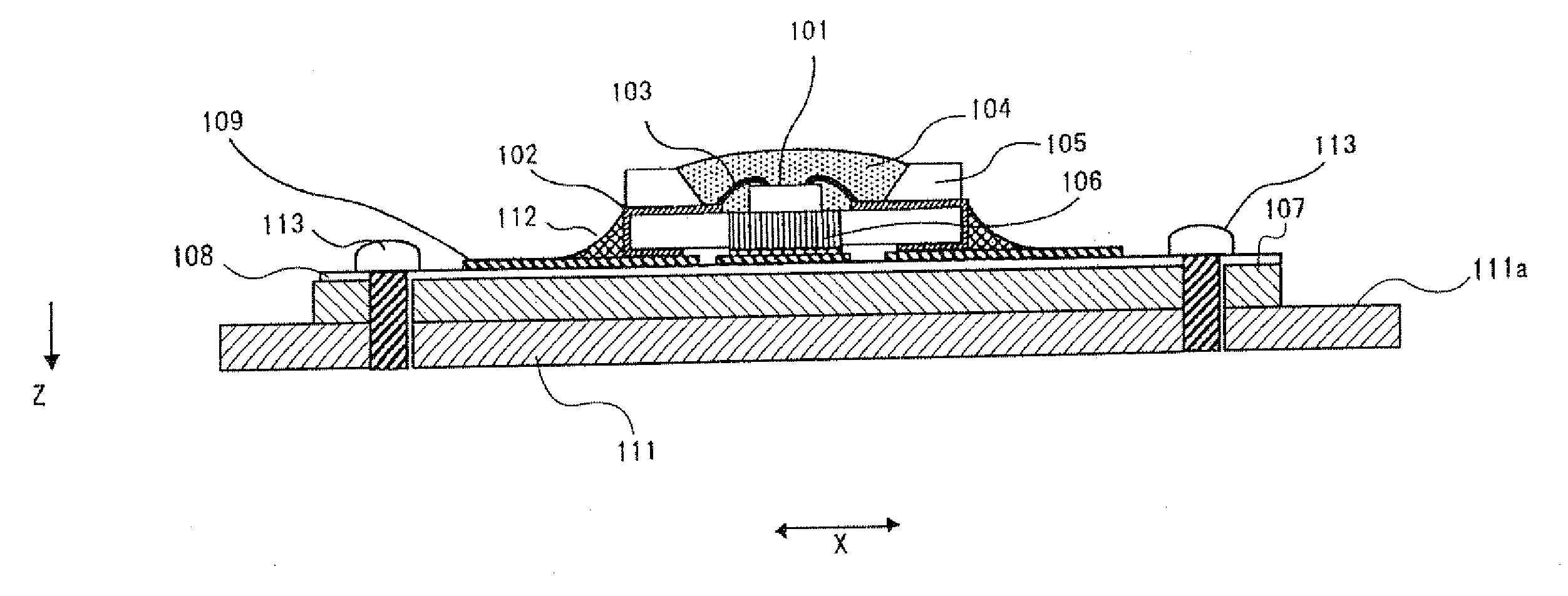
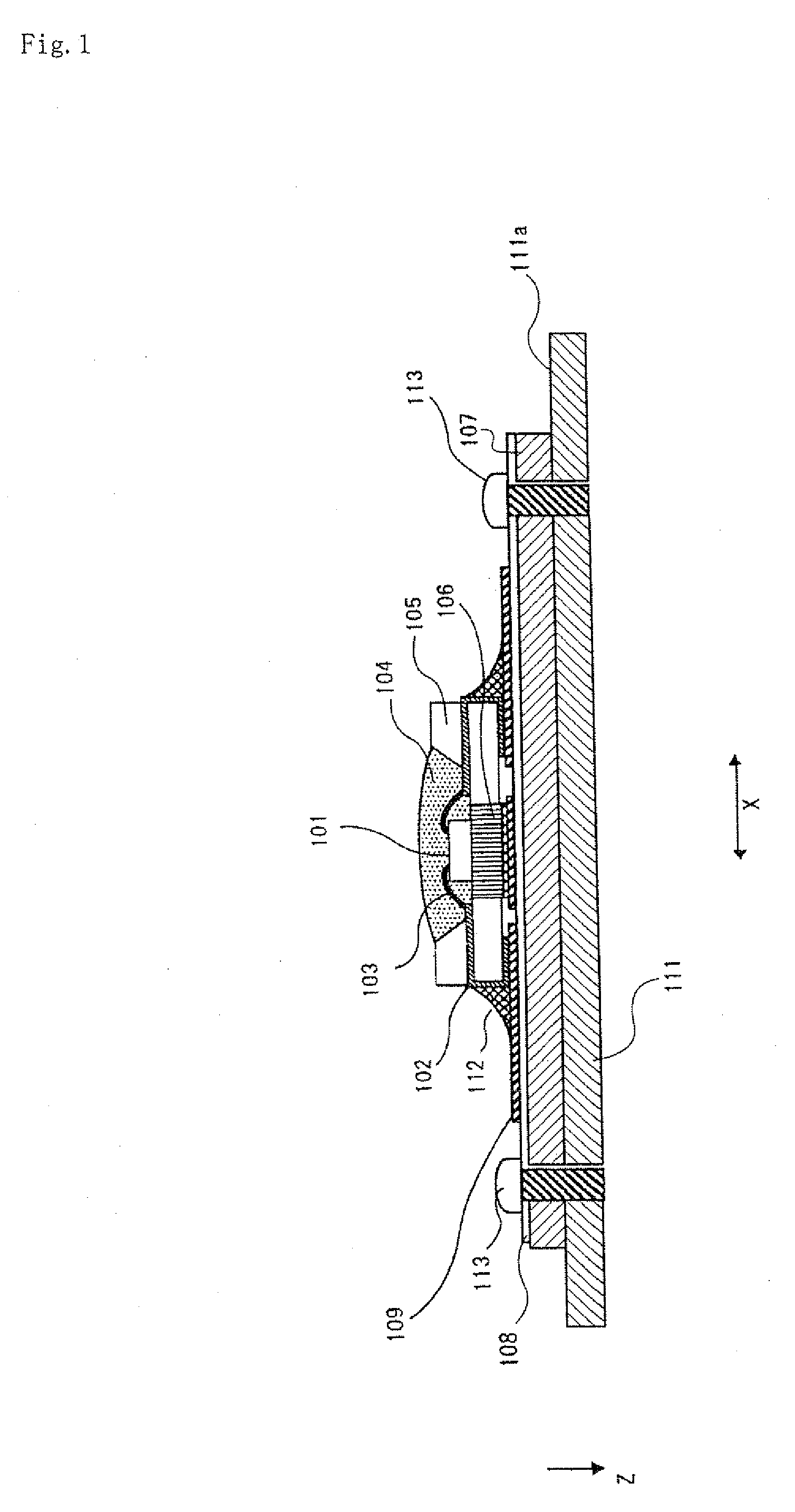
[0025]FIG. 1 is a schematic, side cross-section view of a lighting device of the present exemplary embodiment.

[0026]Lighting device 30 of the present invention includes light emitting unit 20 having LED chip 1, which is a light emitting element, placed on metal core printed circuit board 7 and body 11 where light emitting unit 20 is mounted. Further, graphite is used for body 11 uses. The graphite has anisotropic heat conductivity. The anisotropy has a first direction having a first heat conductivity and a second direction having a second heat conductivity higher than the first heat conductivity. The thickness direction of body 11 of the present exemplary embodiment is oriented to the first direction (direction Z), and a direction parallel to main surface 11a that acts as a heat dissipation surface is set to the second direction (direction X, direction X1 in which heat conductivity is high). Namely, body 11 of the present exemplary embodiment uses graphite so as to enhance the heat ...

second exemplary embodiment

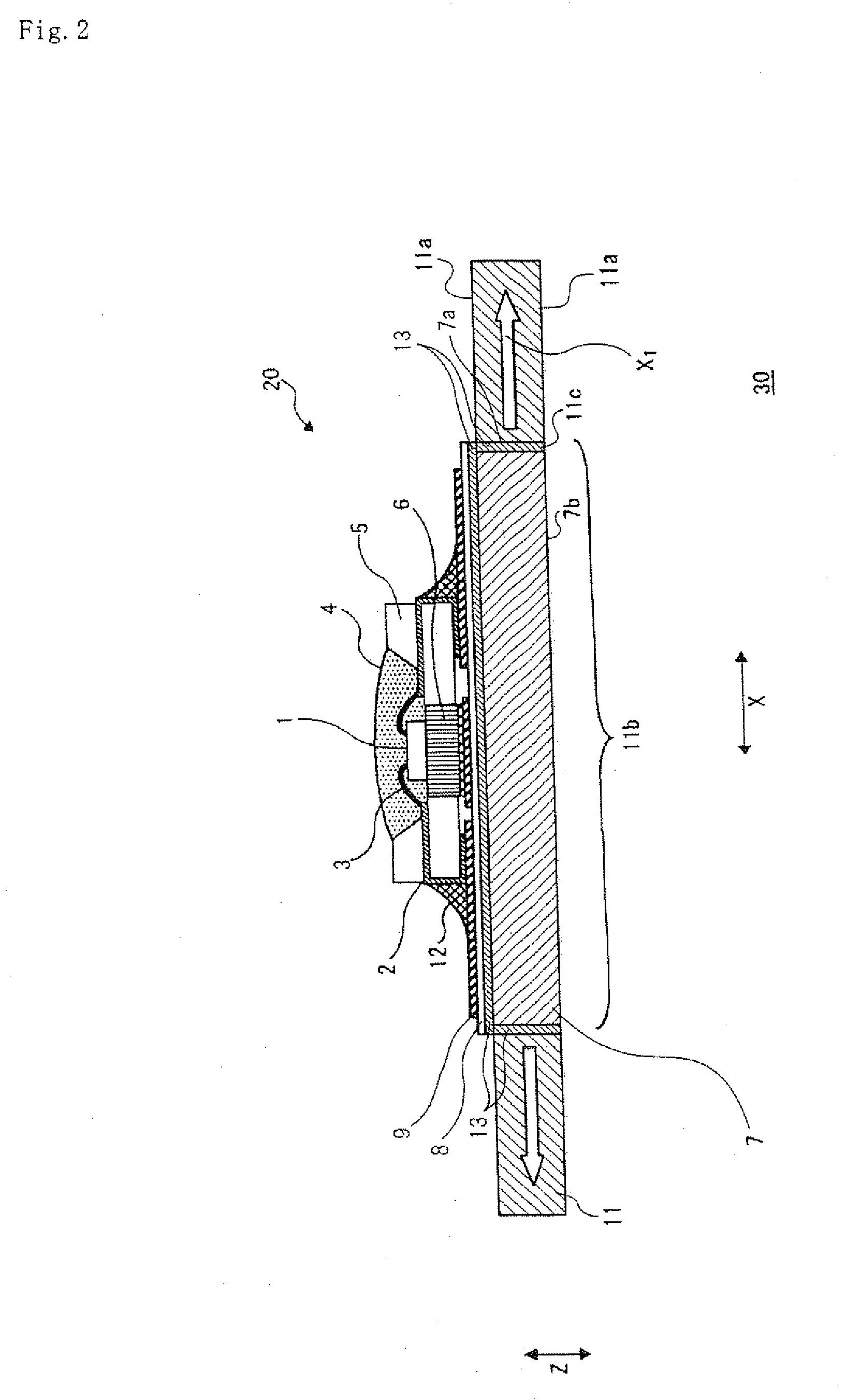
[0040]FIG. 2 is a schematic, side cross-section view of a lighting device of the present exemplary embodiment.

[0041]A basic configuration of the lighting device of the present exemplary embodiment is similar to that of the lighting device shown in the first exemplary embodiment. Namely, body 11 is configured so that direction X1 in which heat conductivity is high, similarly to the first exemplary embodiment, is set to be parallel to main surface 11a, but differs in that metal core printed circuit board 7 is threaded into bore 11b rather than being inserted by press fitting. In addition, the other components having the same configuration are indicated by like symbols, and overlapped description will be omitted.

[0042]A side wall of metal core printed circuit board 7 is tapped to produce male thread 7c, and an inner wall of bore 11b of body 11 is also tapped to produce female thread 11d. Then, metal core printed circuit board 7 is threaded into bore 11b of body 11 and attached. In addi...


PUM

PropertyMeasurementUnit
densityaaaaaaaaaa
densityaaaaaaaaaa
heat conductivityaaaaaaaaaa

Abstract

A fighting device of the present invention includes light emitting unit 20 having a light emitting element installed on a board, and body 11 having light emitting unit 20 mounted thereon. Body 11 has graphite having anisotropic heat conductivity, and the graphite has inner wall 11c in thermal contact with light emitting unit 20. The anisotropy of the graphite has direction Z having a first heat conductivity and direction X1 having a second heat conductivity that is higher than the first heat conductivity. Inner wall 11c of the graphite to which heat generated from light emitting unit 20 is transferred is formed to intersect with direction X1.

Description

TECHNICAL FIELD[0001]The present invention relates to a lighting device including an LED chip as a light emitting element.BACKGROUND TECHNOLOGY[0002]When manufacturing a lighting device and a backlight unit using a solid light emitting device, sufficient heat dissipation is necessary so as not to lower the luminous efficiency of the solid light emitting device.[0003]Generally, a solid light emitting device is implemented on a metal core printed circuit board to be used as a light emitting unit. The light emitting unit is fixed on a metal body of a lighting device by using a screw screwing. Namely, for a heat dissipation structure, the metal body of a lighting device is generally used as a radiator.[0004]In the heat dissipation structure configured as described above, when more heat dissipation is required, a method of enlarging a surface area of the metal body or increasing a thickness thereof can be considered.[0005]The body of a lighting device, generally, is formed of metal such ...

Claims


Application Information

Patent Timeline
Patent Type & Authority Applications(United States)
IPC IPC(8): H01L33/00F21V19/00F21V29/00F21Y101/02
CPCH05K1/0203H05K1/05H05K1/056H05K2201/0323H05K2201/10106F21Y2101/02H01L2224/48091H05K2201/10416F21V19/0055F21V19/003H01L2924/00014F21Y2115/10H01L33/00
Inventor OKIMURA, KATSUYUKI
Owner NEC LIGHTING
Why Eureka
Try Eureka