Substrate processing device

a processing device and substrate technology, applied in the direction of muffle furnaces, separation processes, furnaces, etc., can solve the problems of high cost, troublesome maintenance work, particle contamination of wafers, etc., and achieve excellent creep resistance and high heat conductivity

Inactive Publication Date: 2006-05-25
TOKYO ELECTRON LTD
View PDF12 Cites 8 Cited by
  • Summary
  • Abstract
  • Description
  • Claims
  • Application Information

AI Technical Summary

Benefits of technology

[0011] Preferably, the resin material forming the tubular body is such a material as will not release any matters detrimental to processing a substrate when exposed to an atmosphere of liquid deionized water and gaseous deionized water. Preferably, the resin material forming the tubular body is a fluorocarbon resin, such as PTFE or PFA. More desirably, the resin material forming the tubular body is a composite of PTFE and PFA having excellent creep resistance.
[0012] Preferably, the plate member contacting with or arranged adjacent to the heater is formed of a material having a thermal conductivity higher than that of the resin forming the tubular body, in view of heat transfer from the heater to deionized water contained in the tank. Suitable materials for the plate member having high heat conductivity include metals and amorphous carbon. If the plate member is formed of a metal, it is preferable to provide a coating layer of a resin material on the inner surface facing the interior of the tank in order to prevent the metal from dissolving in the deionized water.

Problems solved by technology

A problem in the conventional substrate processing apparatus is that a metal forming the walls of the tank of the steam generator dissolves in the deionized water, and the dissolved metal flowed together with steam into the processing chamber forms particles, and the particles contaminate the wafer.
Since a large space needs to be formed between the liquid level in the tank and the steam supply line, the dimensional reduction of the tank is limited.
However, Lorimer's steam generator has a complicated construction, is costly and requires troublesome maintenance work.
The coil heater has a narrow surface in contact with a liquid and hence its heating efficiency is low.
It is possible that the Teflon coating is subject to deterioration with time.

Method used


Image

  • Substrate processing device
  • Substrate processing device
  • Substrate processing device

Examples


Embodiment Construction

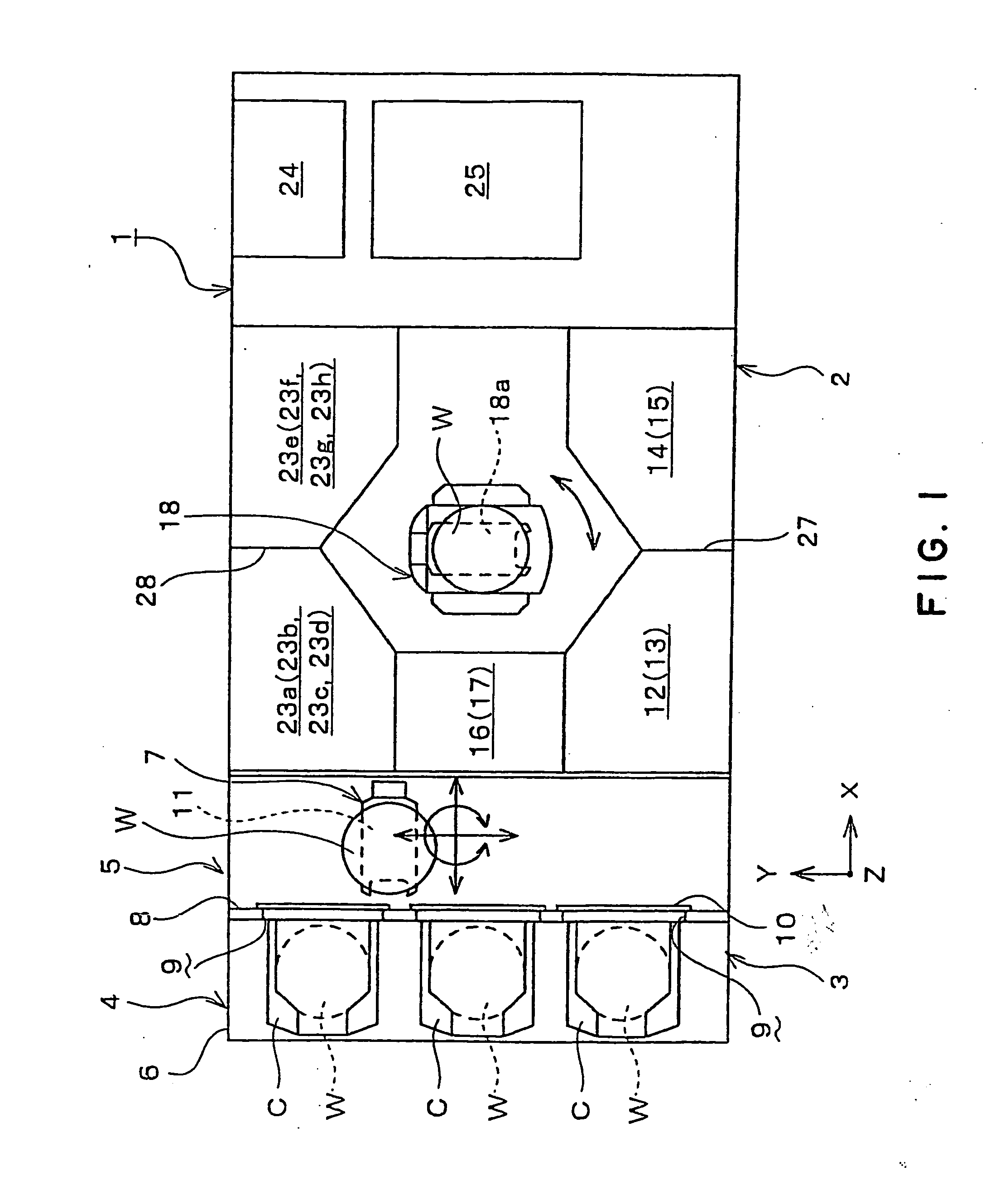
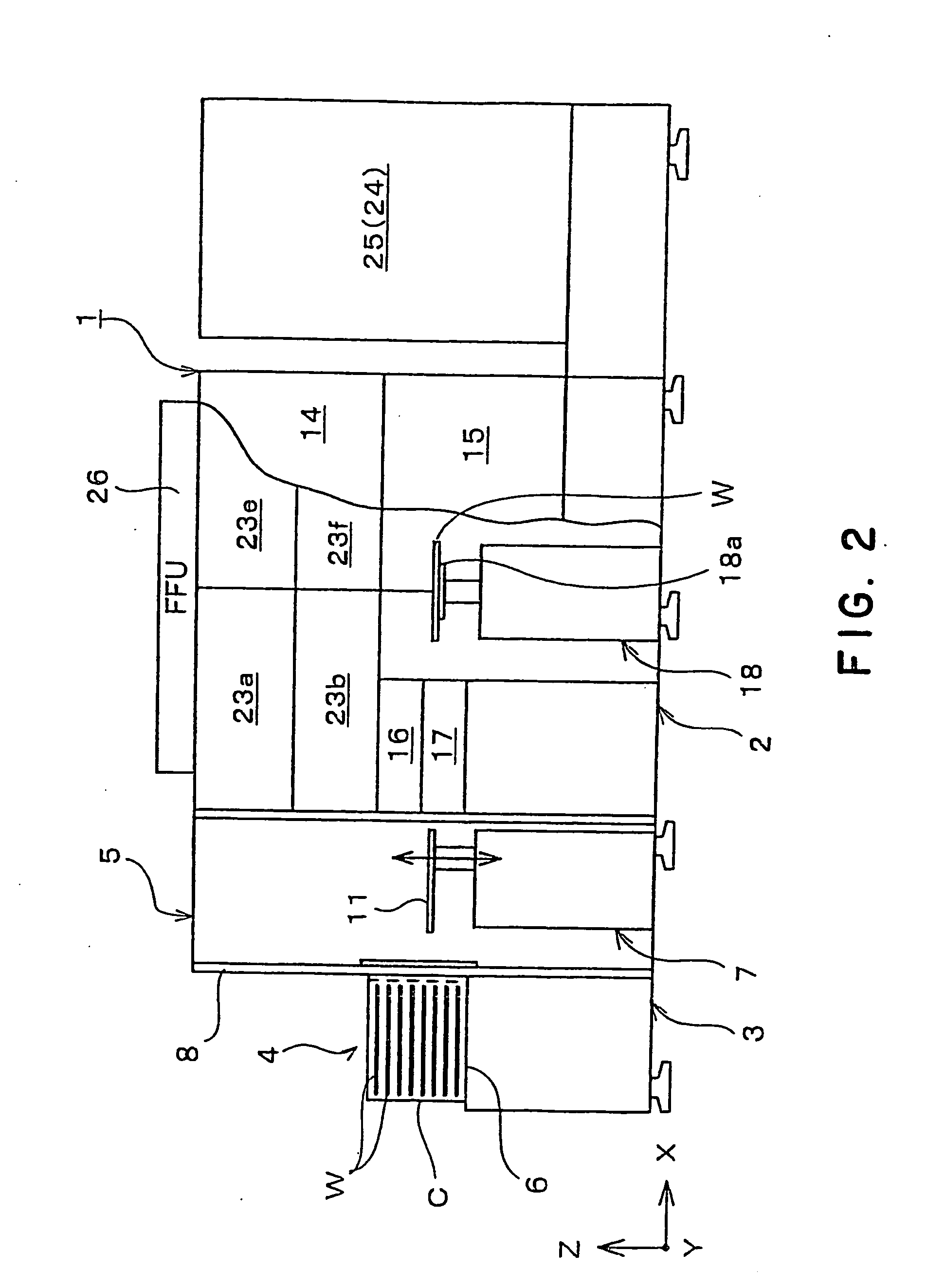
[0044] A preferred embodiment of the present invention will be described in terms of a substrate processing unit, as a substrate processing apparatus according to the present invention, as applied to making a resist applied to a surface of a wafer, as an example of a substrate, water-soluble. FIG. 1 is a plan view of a processing system 1 provided with substrate processing units 23a to 23h. FIG. 2 is a side elevation of the processing system 1. The processing system 1 has a processing section 2 for processing a wafer W by a cleaning process and a resist solubilizing process and a wafer carrying-in-out section 3 for carrying a wafer W into and carrying a wafer W from the processing section 2.

[0045] The wafer carrying-in-out section 3 includes: an in-out port 4 provided with a table 6 to support thereon carriers C each capable of holding a plurality of substantially disk-shaped wafers W, for example twenty-five wafers W in a substantially horizontal position at predetermined vertical...


PUM

PropertyMeasurementUnit
thicknessaaaaaaaaaa
temperatureaaaaaaaaaa
pressureaaaaaaaaaa

Abstract

A steam generator 40′ provided in a substrate processing apparatus includes a tank 301 having a hollow cylindrical member 302 formed of a composite of PTFE and PFA and a pair of side wall plates 303 connected to the opposite ends of the cylindrical member 302. The tank 301 is surrounded by a shell 305 of an aluminum alloy to prevent deformation of the tank due to internal pressure of the tank. A heater 308 is attached to the outer surfaces of the plate members 307 of the shell 305. The shell 305 restrains the tank 301 and compresses elastic sealing members 305 to sealingly engage the cylindrical member 302 and the side wall plate 303 with each other.

Description

TECHNICAL FIELD [0001] The present invention relates to a substrate processing apparatus using steam for processing a substrate, such as a semiconductor wafer or a glass for an LCD substrate. BACKGROUND ART [0002] A series of steps of a semiconductor device fabricating process includes a step of removing a resist coated on a surface of a semiconductor wafer. A known resist removing method makes a resist water-soluble and washes it out with deionized water. A process for making the resist water-soluble uses a substrate processing apparatus, which holds the wafer in a processing chamber, and supplies a mixed process fluid of ozone gas and steam into the processing chamber to make the resist into water-soluble by oxidizing the resist with the mixed process fluid. The substrate processing apparatus is provided with a steam generator that heats deionized water stored in a tank to generate steam to be supplied into the processing chamber. Steam generated by heating the deionized water in ...

Claims


Application Information

Patent Timeline
Patent Type & Authority Applications(United States)
IPC IPC(8): B01D7/00H01L21/00
CPCH01L21/67051Y10S134/902H01L21/304
Inventor ITO, NORIHIROKAWAGUCHI, HIROAKICHOUNO, YASUHIRO
Owner TOKYO ELECTRON LTD
Why Eureka
Try Eureka