Light-emitting apparatus

a technology of light-emitting devices and light-emitting devices, which is applied in the direction of discharge tubes/lamp details, discharge tubes luminescnet screens, electric discharge lamps, etc., can solve the problems of light-emitting devices deterioration, inferior luminescence, and light-emitting apparatus damage, and achieve high heat conductivity

Inactive Publication Date: 2007-09-11
SEMICON ENERGY LAB CO LTD
View PDF63 Cites 8 Cited by
  • Summary
  • Abstract
  • Description
  • Claims
  • Application Information

AI Technical Summary

Benefits of technology

[0010]In the present invention, for solving the above described problems, an inorganic film is formed after forming a light-emitting device, and a film containing fluoroplastics is formed thereon with avoiding contact with a metal material for forming the light-emitting device, as the result, a metal material corrosion due to fluorine in the film containing fluoroplastics can be prevented.
[0011]In the present invention, an inorganic insulating film formed between a metal film of a light-emitting device (a second electrode) and a film containing fluoroplastics has a function of preventing fluorine in the film containing fluoroplastics from reacting to the metal material (barrier property), in addition, the inorganic insulating film is formed of a material having high heat conductivity for releasing heat generated in a light-emitting device. Specifically, an inorganic material such as silicon nitride, silicon oxynitride (SiNxOy), silicon oxide, aluminum nitride (AlN), aluminum oxynitride (AlNxOy), DLC (diamond like carbon) film, carbon nitride (CxNy) film, or the like is useful for the inorganic insulating film.

Problems solved by technology

However, a light-emitting apparatus has a problem in the fabrication process, the problem is different from that of another display apparatuses such as a liquid crystal display apparatus, or the like.
It is known that a light-emitting device is deteriorated by moisture.
Specifically, due to moisture, exfoliation between an electroluminescent layer and a electrode, deterioration of a material for forming an electroluminescent layer, generation of non light emitting portion referred to as a dark spot, or shrinkage of a light emitting portion resulting to inferior luminescence are seen in the light-emitting device.
Such deterioration of the light-emitting device causes decreasing reliability of a light-emitting device in a long-time-driving.
Although the relative permittivity of Teflon® can be controlled to be from 1.9 to 2.1, there are concerns over ramifications of using Teflon® such as the thermal stability, metal fluorine reaction, or the like.
Accordingly, there are problems that heat generated in a light-emitting device can not be released or a metal materials (an electrode or a wiring or the like) for forming the light-emitting device is corroded in the case of forming directly Teflon®AF on the device.

Method used


Image

  • Light-emitting apparatus
  • Light-emitting apparatus
  • Light-emitting apparatus

Examples


embodiment mode 2

[0058]In Embodiment Mode 2, measured results of the characteristics of the film containing fluoroplastics used in the present invention will be described. A film used for the measurement is the film containing fluoroplastics formed to have a thickness of 100 nm by using target of polytetrafluoroethylene by sputtering under the conditions, that is, Ar gas used as process gas is 30 sccm; sputtering pressure used is 0.4 Pa; electric power, 400 W; and the substrate temperature, 300° C.

[0059]FIG. 6 is a view showing spectrums of ESCA (photoelectron spectroscopy for chemical analysis). Chemical composition of fluoride, oxygen, carbon, and silicon in the sample is in a ratio of 61:<1:38:<0.

[0060]Measured results of a film formed by much the same measuring method in a different deposition condition is illustrated in FIG. 7. In this case, 30 sccm Ar gas and 5 sccm O2 gas are introduced. The composition ratio is the same as the condition illustrated in FIG. 6.

[0061]FIG. 8 is a graph showing q...

embodiment mode 3

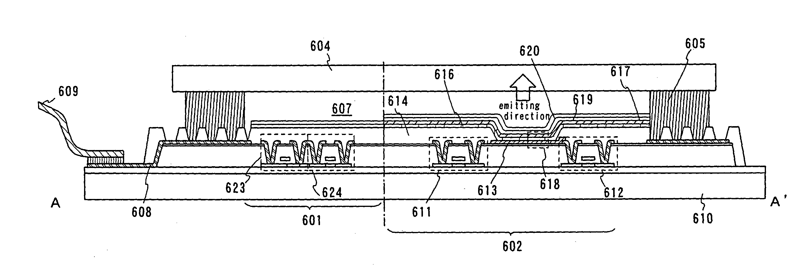
[0062]In Embodiment Mode 3, the external view of an active matrix type light-emitting apparatus will be described with reference to FIG. 4. FIG. 4A is a top surface view of a light-emitting apparatus and FIG. 4B is a cross-sectional view taken along the line of A-A′ of FIG. 4A. Reference numeral 601 indicated by a dotted line is a drive circuit portion (a source side drive circuit), 602 is a pixel portion, 603 is a drive circuit portion (a gate side drive circuit), 604 is a sealing substrate, 605 is a sealing agent, and 607 surrounded by the sealing agent 605 is a space.

[0063]Reference numeral 608 is a wiring for transmitting signals to be inputted to the source side drive circuit 601 and a gate side drive circuit 603. The wiring 608 receives a video signal, a clock signal, a start signal, a reset signal, or the like from the FPC (a flexible printed circuit) 609 that serves as an external input terminal. Though only the FPC is illustrated here, a PWB (a print wiring board) can be at...

embodiment mode 4

[0080]Since the light-emitting apparatus using a light-emitting device is a self-luminous type, it has high visibility in a light place and a wide viewing angle compared with a liquid crystal display apparatus. Therefore various electric appliances can be completed by employing the light-emitting apparatus according to the present invention.

[0081]Given as examples of electric appliances employing a light-emitting apparatus fabricated according to the present invention are: a video camera; a digital camera; a goggle type display (head mounted display); a navigation system; an audio reproducing device (car audio, an audio component, etc.); a laptop computer; a game machine; a portable information terminal (a mobile computer, a cellular phone, a portable game machine, an electronic book, etc.); and an image reproducing device (specifically, a device that is equipped with a display device for reproducing data in a recording medium such as a digital versatile disk (DVD)). The light-emitt...


PUM

PropertyMeasurementUnit
relative permittivityaaaaaaaaaa
work functionaaaaaaaaaa
thicknessaaaaaaaaaa

Abstract

The present invention is to solve the problems of heat release and a metal material corrosion due to fluorine that are arisen in the case of using a film containing fluoroplastics (Teflon®) as a protective film for a light-emitting device. In the present invention, an inorganic film is formed after forming a light-emitting device, and a film containing fluoroplastics is formed thereon for avoiding contact with a metal material for forming the light-emitting device, as a result, a metal material corrosion due to fluorine in the film containing fluoroplastics can be prevented. In addition, the inorganic insulating film has a function of preventing fluorine in the film containing fluoroplastics from reacting to the metal material (barrier property), in addition, the inorganic insulating film is formed of a material having high heat conductivity for releasing heat generated in a light-emitting device.

Description

BACKGROUND OF THE INVENTION[0001]1. Field of the Invention[0002]The present invention relates to a light-emitting apparatus comprising a light-emitting device, which emits fluorescent light or phosphorescent light upon application of an electric field thereto, including a pair of electrodes and an electroluminescent layer that is sandwiched between the pair of electrodes, and to a method of fabricating the light-emitting apparatus. Particularly, the present invention relates to technique for preventing moisture or oxygen from penetrating into the light-emitting device formed on a substrate by using a film containing fluoroplastics. In this specification, the term light-emitting apparatus includes an image display apparatus, a light-emitting device, or a light source (including a lighting system). Also, the following modules are included in the light-emitting apparatus: a module obtained by attaching a connector such as an FPC (flexible printed circuit), a TAB (tape automated bonding...

Claims


Application Information

Patent Timeline
Patent Type & Authority Patents(United States)
IPC IPC(8): H05B33/12H05B33/04H01L27/32H01L51/50H01L51/52H05B33/10
CPCH01L51/529H01L51/5237H01L27/3244H10K59/12H10K50/8426H10K50/87H10K50/844
Inventor YAMAZAKI, SHUNPEITAKAYAMA, TORUTSURUME, TAKUYAGOTO, YUUGO
Owner SEMICON ENERGY LAB CO LTD
Why Eureka
Try Eureka