Fluid sensing in a drip tray

a drip tray and fluid sensing technology, applied in the direction of liquid handling, packaging, cap, etc., can solve the problems of cumbersome use, complex construction and/or construction, and high manufacturing cost of conventional commercial appliances and some consumer appliances, and achieve the effect of minimizing the amount of wasted bag material and improving the heat sealing operation of vacuum packaging appliances

Inactive Publication Date: 2005-02-24
TILIA INT INC
View PDF71 Cites 71 Cited by
  • Summary
  • Abstract
  • Description
  • Claims
  • Application Information

AI Technical Summary

Benefits of technology

[0012] The present invention therefore protects the vacuum packaging appliance and also greatly enhances the heat sealing operations of vacuum packaging appliances based on the detected amount of liquid which minimizes the amount of wasted bag material due to faulty sealing.

Problems solved by technology

Conventional commercial appliances and some consumer appliances are generally expensive to manufacture, complex in construction and / or cumbersome to operate.
Although adaptable for low-volume home use, this type of appliance is cumbersome to use and normally requires a liquid separator or filter to prevent liquids or powders, retained within the bag, from being drawn into a vacuum pump connected to the nozzle.
A substantial problem with these and other prior art vacuum packaging appliances is that liquids evacuated from the bag contents collect in the vacuum chamber and may damage the vacuum pump itself.
The presence of these unwanted liquids also causes failures in the heat sealing operations.
Energy supplied to the heat sealing elements is wasted on burning off these unwanted liquids, therefore the temperature of the inside layer of the bag does not reach the required level for heat sealing to occur.

Method used


Image

  • Fluid sensing in a drip tray
  • Fluid sensing in a drip tray
  • Fluid sensing in a drip tray

Examples


Embodiment Construction

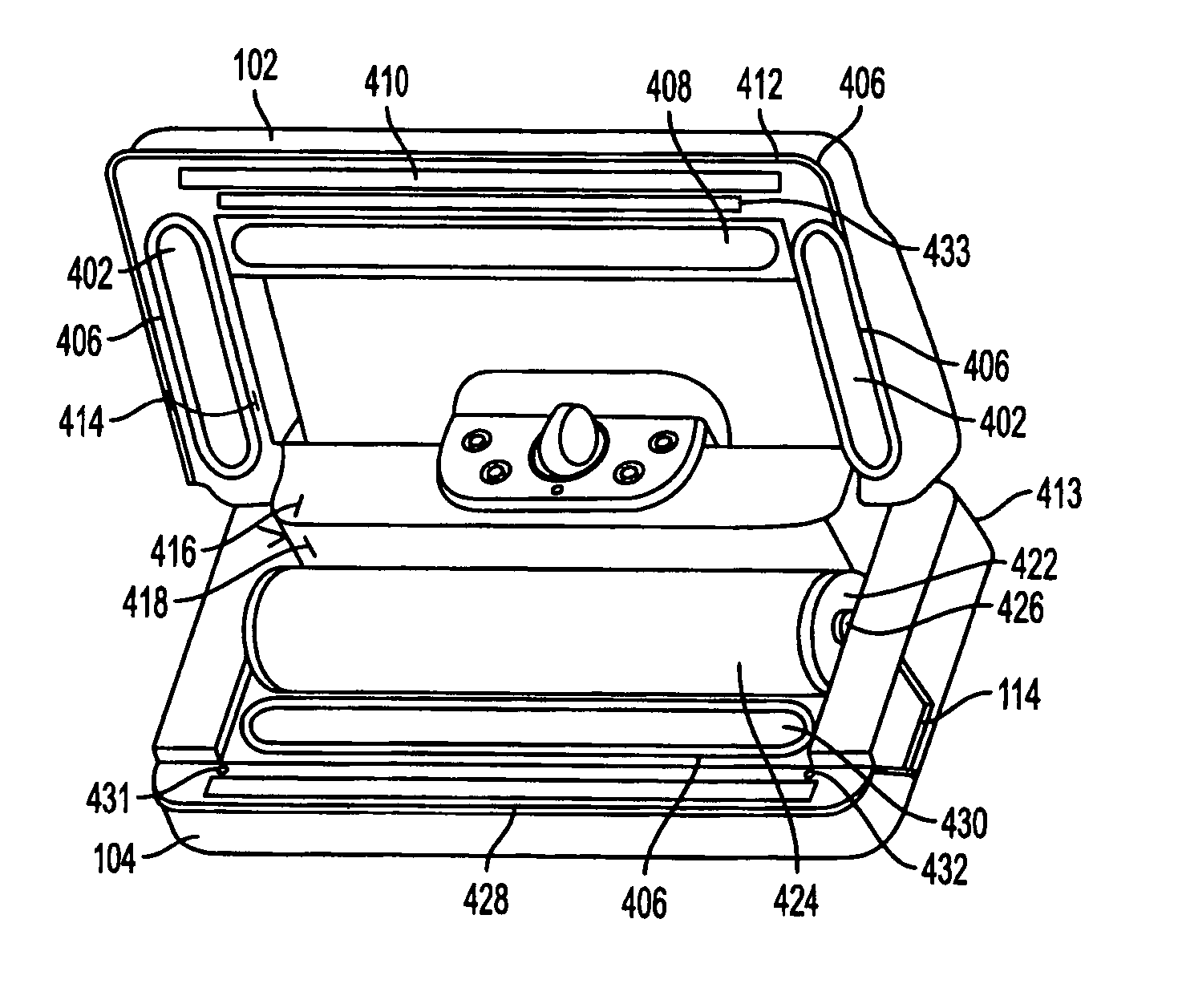
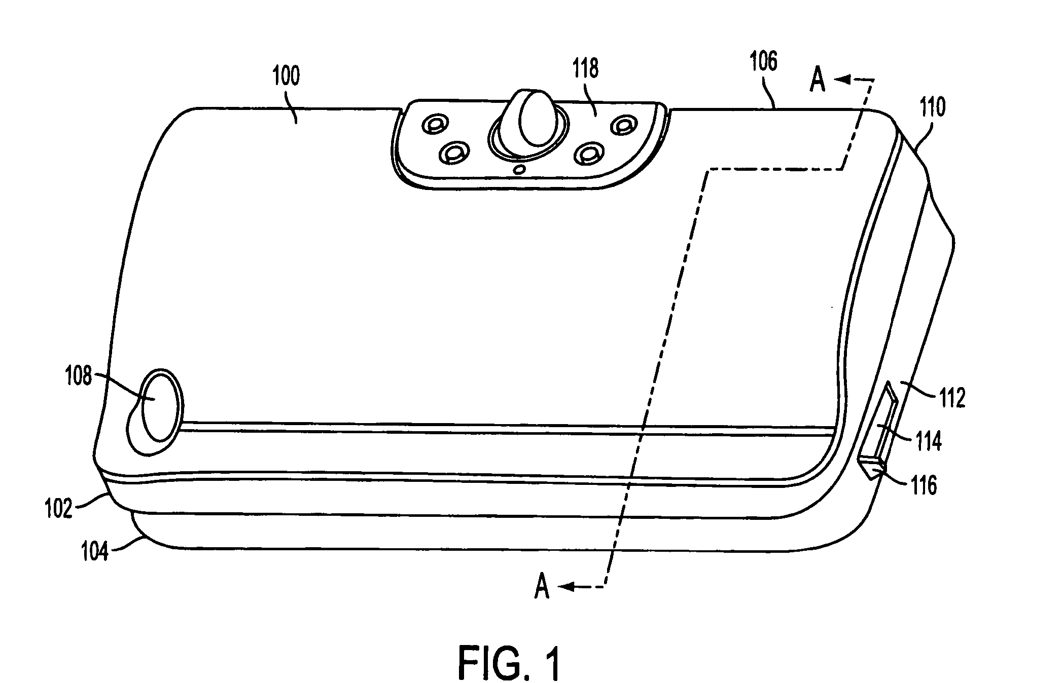
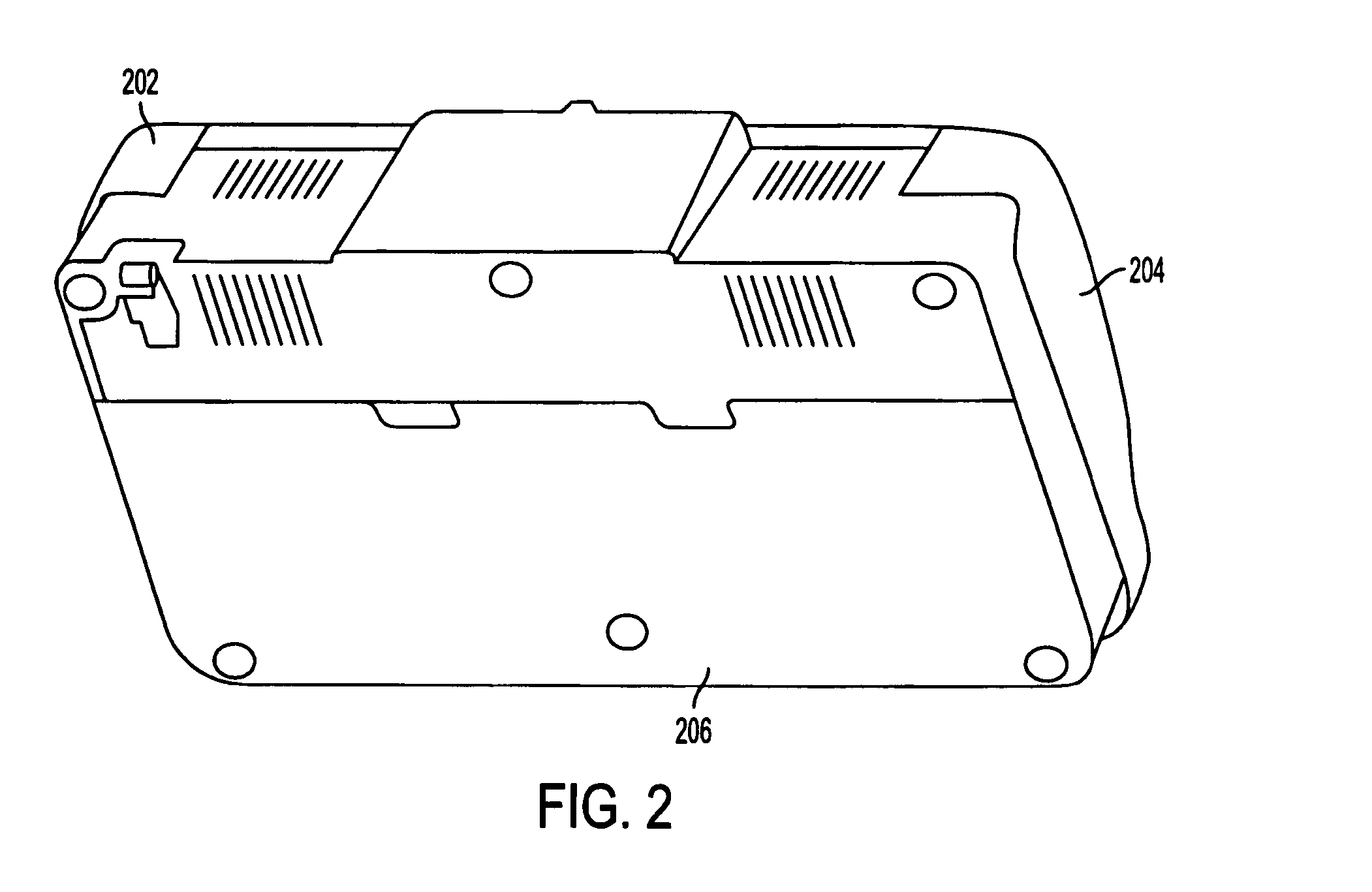
[0029] For clarity of presentation, the FIGS. are grouped and discussed as follows. FIGS. 1-4 describe general features and structures of the present invention relating to a vacuum packaging appliance. FIGS. 5-9 focus on the liquid sensing and controlling structures of the appliance and their interaction with the structures described in FIGS. 1-4. FIGS. 10-12 show flowcharts of methods enacted by the present invention.

[0030]FIG. 1 shows a vacuum packaging appliance 100 for vacuum packaging articles in a container that includes a liquid sensing capability. The vacuum packaging appliance 100 has a lid 102 and a base 104 that are pivotally connected at a back side 106 of the appliance 100. However, in alternate embodiments the lid and base maybe connected in any other convenient manner or they may be independent parts.

[0031] The lid includes a blade handle 108 that is associated with a blade (not shown) on the inside of the lid 102 of the vacuum packaging appliance 100. The blade han...


PUM


Abstract

A vacuum packaging appliance that detects the amount of liquid present while evacuating and sealing a container is disclosed. The appliance comprises a lid adapted to define a vacuum chamber when it is moved to a closed position relative to a trough in the base of the device. The trough in the lower portion of the device contains a heat-sealing element used to seal the contents of the bag once the vacuum packaging is complete. Disclosed are several embodiments relating to a liquid sensor molded into the walls of the trough. The liquid sensor comprises two electrodes that may be located on opposite sides of the trough or on the same side of the trough. When liquid is present in the trough, the capacitance and resistance between the electrodes changes, thereby sending a signal to a controller indicative of the amount of liquid within the trough while the container is being evacuated. The exact amount of liquid present is compared to a predetermined level of liquid. A vacuum pump controller may suspend operations if the amount of detected liquid exceeds a predetermined amount. The heat-sealing element is also controlled in accordance with the amount of liquid sensed in the trough. The amount of liquid sensed is also indicated to the operator.

Description

CROSS-REFERENCE TO RELATED APPLICATIONS [0001] The present application claims priority to Albritton et al.'s U.S. provisional application No. 60 / 492,046, filed Jul. 31, 2003, and entitled FLUID SENSING IN A DRIP TRAY, the contents of which are incorporated herein by reference. The present application is also related to Albritton et al's U.S. provisional application No. 60 / 491,876, filed Jul. 31, 2003, and entitled HEAT SEALING ELEMENT AND CONTROL OF SAME, the contents of which are incorporated herein by reference.TECHNICAL FIELD [0002] The invention relates to a vacuum packaging appliance for packaging products and more particularly to sensing liquid in a trough of the vacuum packaging appliance while evacuating a container and controlling a vacuum pump and heat sealing elements in accordance with the detected amount of liquid. BACKGROUND OF THE INVENTION [0003] Presently, various appliances and methods are used for the purpose of vacuum sealing plastic bags and containers to protec...

Claims


Application Information

Patent Timeline
Patent Type & Authority Applications(United States)
IPC IPC(8): B65B31/00B65B31/04B65B67/00
CPCB65B31/046B65B31/00
Inventor ALBRITTON, CHARLES WADEHIGER, LANDENPETERS, JOHN
Owner TILIA INT INC
Why Eureka
Try Eureka