
Integrated active flux microfluidic devices and methods

a microfluidic device and active flux technology, applied in the direction of fluid speed measurement, positive displacement liquid engine, flow mixer, etc., can solve the problems of large sample volume, high cost, time-consuming and labor-intensive, and conventional techniques are expensive and labor-intensive, so as to achieve rapid and complete sample exposure, quick and accurate analysis, and low cost

Inactive Publication Date: 2004-12-09
CALIFORNIA INST OF TECH
View PDF99 Cites 254 Cited by
  • Summary
  • Abstract
  • Description
  • Claims
  • Application Information

AI Technical Summary

Benefits of technology

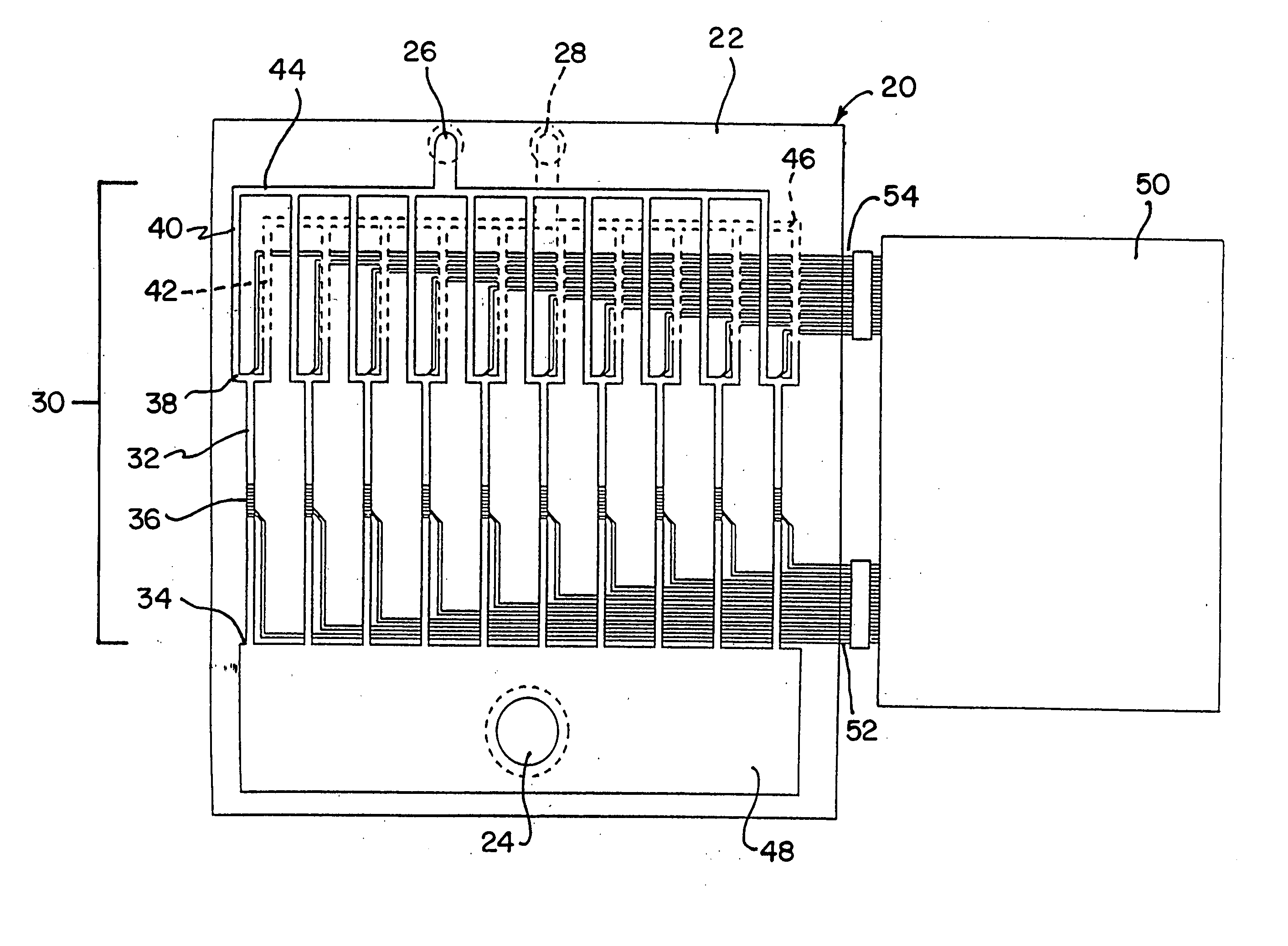
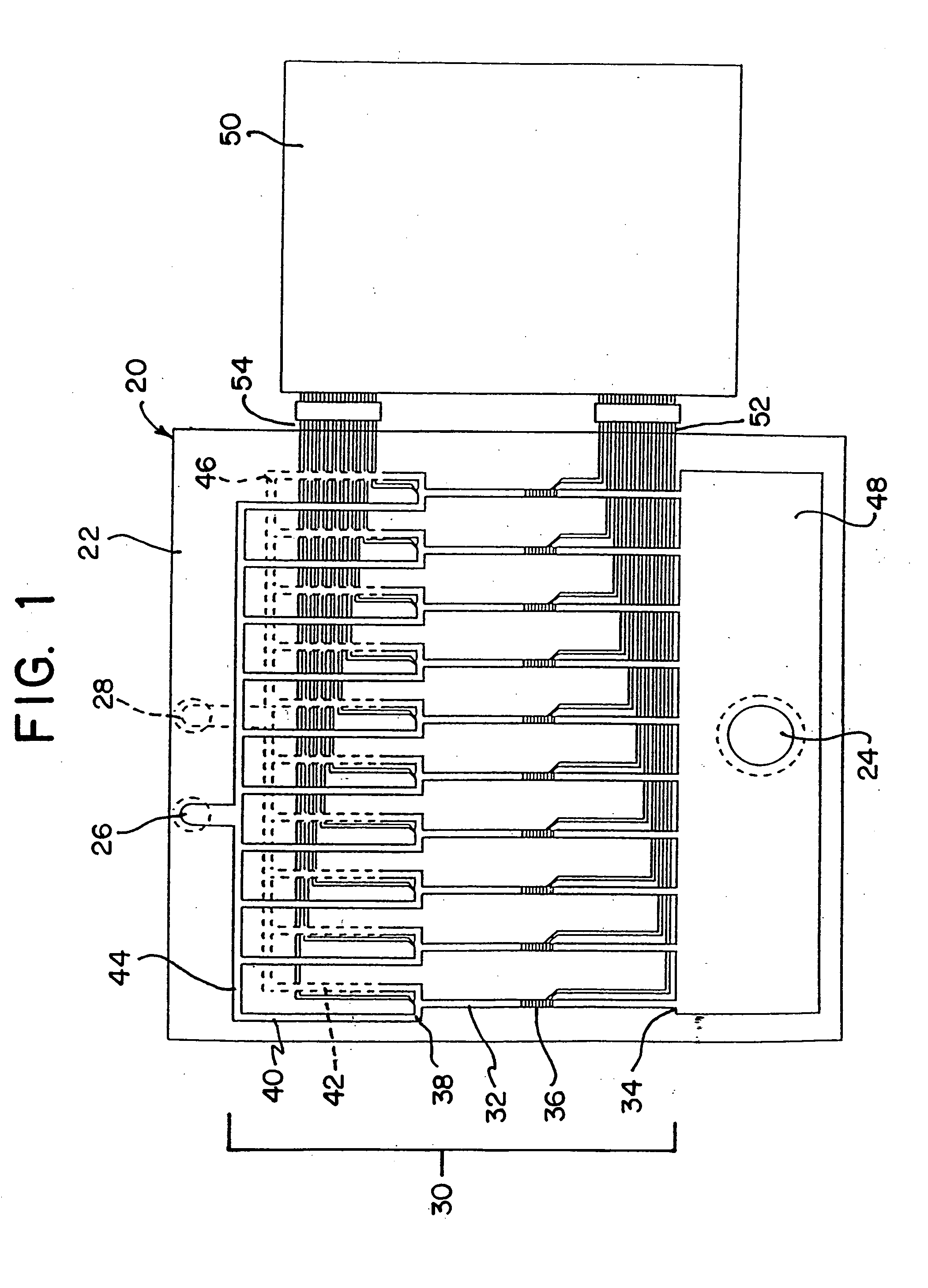
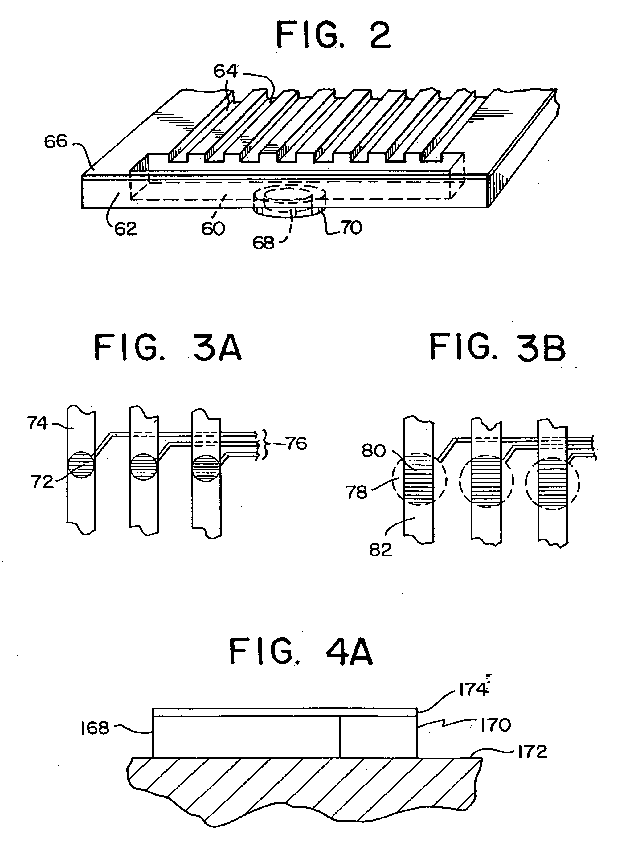
The invention provides microdevices and methods for quickly detecting DNA, proteins, viruses, or other molecules or particles associated with a particular disease. The devices include a chip with a microfabricated analysis unit, with multiple channels for detecting molecules or particles. The channels are patterned with target molecules or polynucleotides, and may be interconnected or placed in separate channels. The devices also include a peristaltic pump for controlling flow or delivering reagents or samples. The invention also provides a multilayer device with separate channels for treatment and control, and valves for controlling flow and interactions between channels. The valves have low dead volumes and can be actuated with minimal hysteresis, making them ideal for microfluidic metering and control.

Problems solved by technology

However, relatively large sample volumes have been necessary and significant manipulation of the sample may be required.
The conventional techniques are costly, time consuming and very labor-intensive.
These methods may not work when only small samples are available.
Rapid, contemporaneous, or simultaneous testing for more than one organism, disease characteristic, or parameter may be impractical or impossible.
A further drawback is that is that the diffusion constant of DNA fragments is small, on the order of .about.10.sup.-7 cm.sup.2 / sec for 1-kbp DNA fragments (5).
Thus, passive diffusion is an extremely slow process for large molecules such as DNA.
Therefore, it takes a relatively long time for target DNA to be directed to complementary DNA probes.
DNA may be lost or fail to find a matching probe, or will not do so in a reasonable time.
PCR amplification may be needed to obtain enough DNA sample, which complicates the process and gives new sources of possible errors.
The process can be time consuming, and resolution is typically about 10%.
Efficiency and resolution decrease as the size of fragments increases; molecules larger than 40,000 base pairs are difficult to process, and those larger than 10 million base pairs cannot be distinguished.
This method requires that the radiation exciting the dye molecules, and the emitted fluorescence, must traverse the sheath fluid, leading to poor light collection efficiency and resolution problems caused by lack of uniformity.
Specifically, this method results in a relatively poor signal-to-noise ratio of the collected fluorescence, leading to inaccuracies in the sizing of the DNA molecules.
This method, employs costly and cumbersome equipment, and requires atomization of the nucleic acid solution into droplets, where each droplet contains at most one analyte molecule.
Furthermore, the flow velocities required for successful sorting of DNA fragments were determined to be considerably slower than used in conventional flow cytometry, so the method would require adaptations to conventional equipment.
Sorting a usable amount (e.g., 100 ng) of DNA using such equipment would take weeks, if not months, for a single run, and would generate inordinately large volumes of DNA solution requiring additional concentration and / or precipitation steps.

Method used


Image

  • Integrated active flux microfluidic devices and methods
  • Integrated active flux microfluidic devices and methods
  • Integrated active flux microfluidic devices and methods

Examples


Embodiment Construction

5.1. Definitions

[0097] The terms used in this specification generally have their ordinary meanings in the art, within the context of the invention, and in the specific context where each term is used. For example, conventional techniques of molecular biology, microbiology and recombinant DNA techniques may be employed in accordance with the present invention. Such techniques and the meanings of terms associated therewith are explained fully in the literature. See, for example, Sambrook, Fitsch & Maniatis, Molecular Cloning: A Laboratory Manual, Second Edition (1989) Cold Spring Harbor Laboratory Press, Cold Spring Harbor, N.Y. (referred to herein as "Sambrook et al., 1989"); DNA Cloning: A Practical Approach, Volumes I and II (D. N. Glover ed. 1985); Oligonucleotide Synthesis (M. J. Gait ed. 1984); Nucleic Acid Hybridization (B. D. Hames & S. J. Higgins, eds. 1984); Animal Cell Culture (R. I. Freshney, ed. 1986); Immobilized Cells and Enzymes (IRL Press, 1986); B. E. Perbal, A Pract...


PUM

PropertyMeasurementUnit
diffusion lengthaaaaaaaaaa
diameteraaaaaaaaaa
diameteraaaaaaaaaa

Abstract

The invention relates to a microfabricated device for the rapid detection of DNA, proteins or other molecules associated with a particular disease. The devices and methods of the invention can be used for the simultaneous diagnosis of multiple diseases by detecting molecules (e.g. amounts of molecules), such as polynucleotides (e.g., DNA) or proteins (e.g., antibodies), by measuring the signal of a detectable reporter associated with hybridized polynucleotides or antigen / antibody complex. In the microfabricated device according to the invention, detection of the presence of molecules (i.e., polynucleotides, proteins, or antigen / antibody complexes) are correlated to a hybridization signal from an optically-detectable (e.g. fluorescent) reporter associated with the bound molecules. These hybridization signals can be detected by any suitable means, for example optical, and can be stored for example in a computer as a representation of the presence of a particular gene. Hybridization probes can be immobilized on a substrate that forms part of or is exposed to a channel or channels of the device that form a closed loop, for circulation of sample to actively contact complementary probes. Universal chips according to the invention can be fabricated not only with DNA but also with other molecules such as RNA, proteins, peptide nucleic acid (PNA) and polyamide molecules.

Description

PRIORITY APPLICATIONS[0001] This is a continuation-in-part of copending U.S. patent application Ser. No. 09 / 724,548 filed on Nov. 28, 2000. U.S. patent application Ser. No. 09 / 724,548 claims priority under 35 U.S.C. .sctn. 119(e) to copending U.S. provisional patent application serial Nos. 60 / 209,243; 60 / 211,309; and 60 / 249,360 filed on Jun. 5, 2000; Jun. 13, 2000; and Nov. 16, 2000, respectively. Each of these priority applications hereby incorporated, by reference, in its entirety.1. FIELD OF THE INVENTION[0003] This invention relates to microfluidic devices and methods, including microfabricated multilayer elastomeric devices with active pumps and valves. More particularly, the devices and methods of the invention comprise a loop channel that is selectively open or closed to at least one input or output, and which actively circulates a fluid received in the loop. The loop can be closed by microvalves, for example elastomeric microvalves interposed between an inlet or outlet chann...

Claims


Application Information

Patent Timeline
Patent Type & Authority Applications(United States)
IPC IPC(8): G01N21/64B01F5/06B01F13/00B01F15/02B01L3/00B01L99/00B81B1/00C12M1/00C12N15/09C12Q1/68G01N21/05G01N33/53G01N33/543G01N33/566G01N33/58G01N37/00
CPCB01F5/0646B01L2400/0694B01F13/0072B01F13/0093B01F15/0201B01F15/024B01L3/502707B01L3/50273B01L3/502738B01L3/502761B01L2200/0647B01L2200/10B01L2300/0636B01L2300/0816B01L2300/0861B01L2300/0867B01L2300/088B01L2300/0887B01L2300/123B01L2400/0418B01L2400/043B01L2400/0481B01L2400/0655C12Q1/6816B01F5/0647B01L3/502753B01L3/5027Y10T436/11Y10T436/173845Y10T436/2575Y10T436/145555B01L2400/0638C12Q2565/629Y10T137/0329Y10T137/2224Y10T137/0318Y10T137/2218B01F25/4331B01F25/433B01F33/3022B01F33/3039B01F35/71755B01F35/712B01F35/71805B01F35/717611G01N33/53C12M1/02B01L3/02B01L2200/0689B01L2300/0829
Inventor QUAKE, STEPHEN R.CHOU, HOU-PU
Owner CALIFORNIA INST OF TECH
Learn More