Low bend loss optical fiber

a technology of optical fiber and low-bending, applied in the field of optical fiber, can solve the problems of optical fiber damage, and optical loss and data transmission problems, and achieve the effects of minimizing mode transmission, minimizing the amount of optical loss, and minimizing the chang

Inactive Publication Date: 2011-12-20
SAMSUNG ELECTRONICS CO LTD
View PDF15 Cites 252 Cited by
  • Summary
  • Abstract
  • Description
  • Claims
  • Application Information

AI Technical Summary

Benefits of technology

[0011]The present invention provides optical fibers and a method for manufacturing the same, which can minimize optical loss due to damage by external physical force, such as bending, etc.
[0014]Optical fibers according to the present invention include a clad having a graded refractive index distribution and a trench layer so that the optical fibers can minimize the amount of optical loss due to refractive index change and bending.
[0015]The trench structure of the present invention minimizes mode transmission in the clad by minimizing a change in a refractive index of a single-mode optical fiber. Also, since the optical fiber is constructed in such a manner that the refractive index of a trench layer gradually increases or decreases, it is possible to minimize a wideband bend loss.
[0016]Also, through the trench structure with the graded refractive index distribution, a large-diameter trench layer can be achieved. Besides, the stress caused by such a large-diameter structure can be minimized, and the trench layer may have an entire volume smaller than a conventional round ring structure.
[0017]Also, the optical fiber according to the present invention can minimize even a leaky mode dispersion caused by bending. Besides, through a short cut-off wavelength, it is possible to obtain a wideband low bend loss optical fiber whose bend loss difference is not high in a wide wavelength range of C-band and L-band.

Problems solved by technology

When such a bend loss property is worsened, a problem may be caused in the optical loss and data transmission.
Meanwhile, the communications networks have a problem in that optical fibers are damaged due to external physical force, and optical loss and a problem of data transmission can occur because of the damage to the optical fibers.
However, they have a problem in that they require high manufacturing cost due to a complicated manufacturing process.
Further, it is difficult to connect the holey optical fibers with typical optical fibers of G652 standards, and the holey optical fibers have large optical loss.
Also, optical fibers manufactured by Corning corp. have problems with regard to mechanical strength, splicing loss, and a difficult splicing method, which may be caused by a fine bubble nano structure.
However, there is a problem in that the conventional optical fibers have comparatively inferior optical characteristics in optical loss due to bending.

Method used


Image

  • Low bend loss optical fiber
  • Low bend loss optical fiber
  • Low bend loss optical fiber

Examples


first embodiment

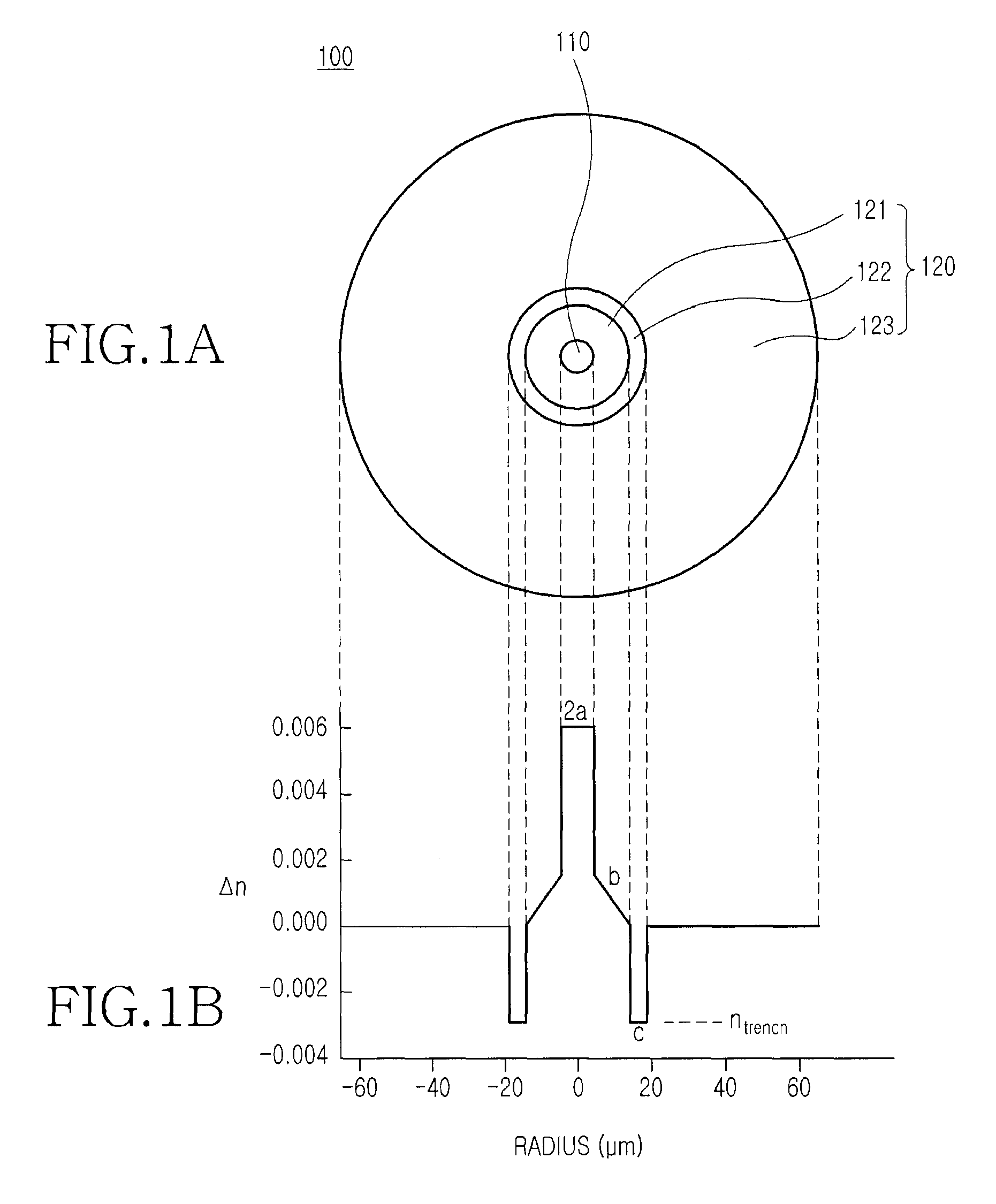
[0023]FIG. 1A is a sectional view of an optical fiber according to the present invention, and FIG. 1B is a graph showing a refractive index profile according to the section of the optical fiber shown in FIG. 1A. Referring to FIG. 1, an optical fiber 100 includes a core 110 and a clad 120. The core 110 is provided at the center of the optical fiber, has a relatively high refractive index, and is for optical signal transmission through total internal reflection. The clad 120 is disposed at the outside of the core 110, and has a relatively low refractive index. In other words, the clad 120 is disposed in such a manner that it can fully surround the core 110 along the circumference of the core 110. The core 110 takes a cylindrical rod shape, and the clad 120 takes a round tube shape. The core 110 and the clad 120 are concentrically disposed.

[0024]The core 110 has a refractive index difference (Δn), which is in the range from 0.0040 to 0.0065. However, it is further preferred that the re...

second embodiment

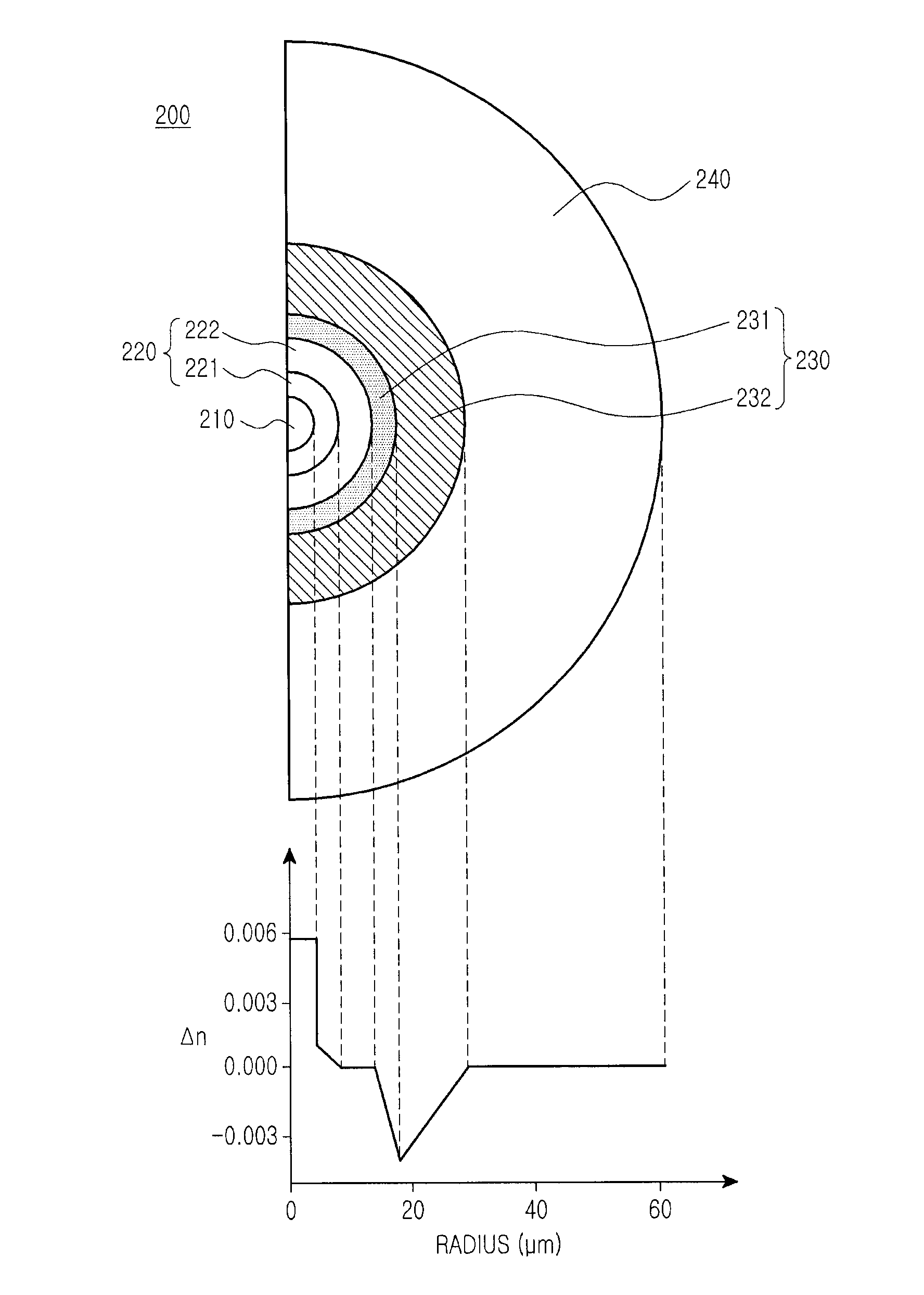
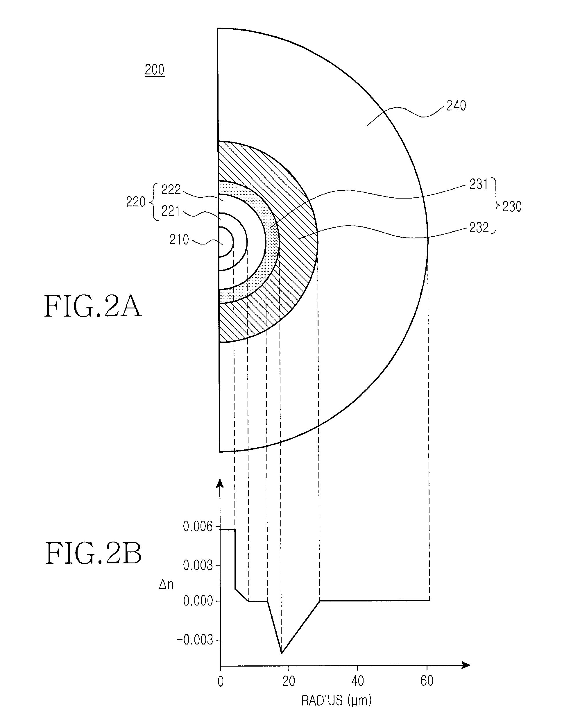
[0042]In the optical fiber 200 of the second embodiment, since the second trench sub layer 232 having a gradually increasing refractive index distribution is disposed within the trench layer 230, the amount of optical loss due to refractive index change and bending may be minimized.

[0043]In the first embodiment, as the thickness of the trench layer 122 increases, a refractive index difference of the optical fiber 100 increases and a bend resistance is enhanced. However, a large-diameter trench structure causes higher-order modes of LP11 or more, thereby increasing a cut-off wavelength of the optical fiber 100. Herein, the cut-off wavelength means a wavelength as a boundary of a single mode from a multi mode. Also, when the thickness of the trench layer 122 is larger than a predetermined value, the cut-off wavelength is out of the range in accordance with G652 standards (1260 nm).

[0044]A calculation equation for a normalized frequency V corresponding to the cut-off wavelength is as f...


PUM


Abstract

Disclosed is a low bend loss optical fiber including: a core; an inner layer disposed at outside of the core, which has a refractive index lower than a refractive index of the core, the refractive index of the inner layer gradually decreasing as it becomes farther from the core; and a trench layer disposed at outside of the inner layer, which has a lowest refractive index.

Description

CLAIM OF PRIORITY[0001]This application claims priority to application entitled “Low Bend Loss Optical Fiber” filed with the Korean Intellectual Property Office on Dec. 19, 2008 and assigned Serial No. 10-2008-0130295, and an application entitled “Low Bend Loss Optical Fiber” filed with the Korean Intellectual Property Office on Nov. 18, 2009 and assigned Serial No. 10-2009-0111472, the contents of both being incorporated herein by reference.BACKGROUND OF THE INVENTION[0002]1. Field of the Invention[0003]The present invention relates to an optical fiber, and more particularly to a low bend loss optical fiber.[0004]2. Description of the Related Art[0005]As an FTTH (Fiber To The Home) subscriber transmission service network of 100 Mbps or more has been recently built, and the related service industries have been activated, the demand for an optical fiber with an enhanced bend resistance for broadband transmission is rapidly increased.[0006]A general passive optical network (PON) for b...

Claims


Application Information

Patent Timeline
Patent Type & Authority Patents(United States)
IPC IPC(8): G02B6/028G02B6/036
CPCG02B6/0283G02B6/0285G02B6/03627G02B6/0365
Inventor YOON, YOUNG-SIKLEE, YEONG-SEOPKIM, JIN-HANHAN, WON-TAEKJOO, SEONG-MINOH, DEA-HWAN
Owner SAMSUNG ELECTRONICS CO LTD
Why Eureka
Try Eureka