Waveguide member and keypad assembly using the same
- Summary
- Abstract
- Description
- Claims
- Application Information
AI Technical Summary
Benefits of technology
Problems solved by technology
Method used
Image
Examples
first embodiment
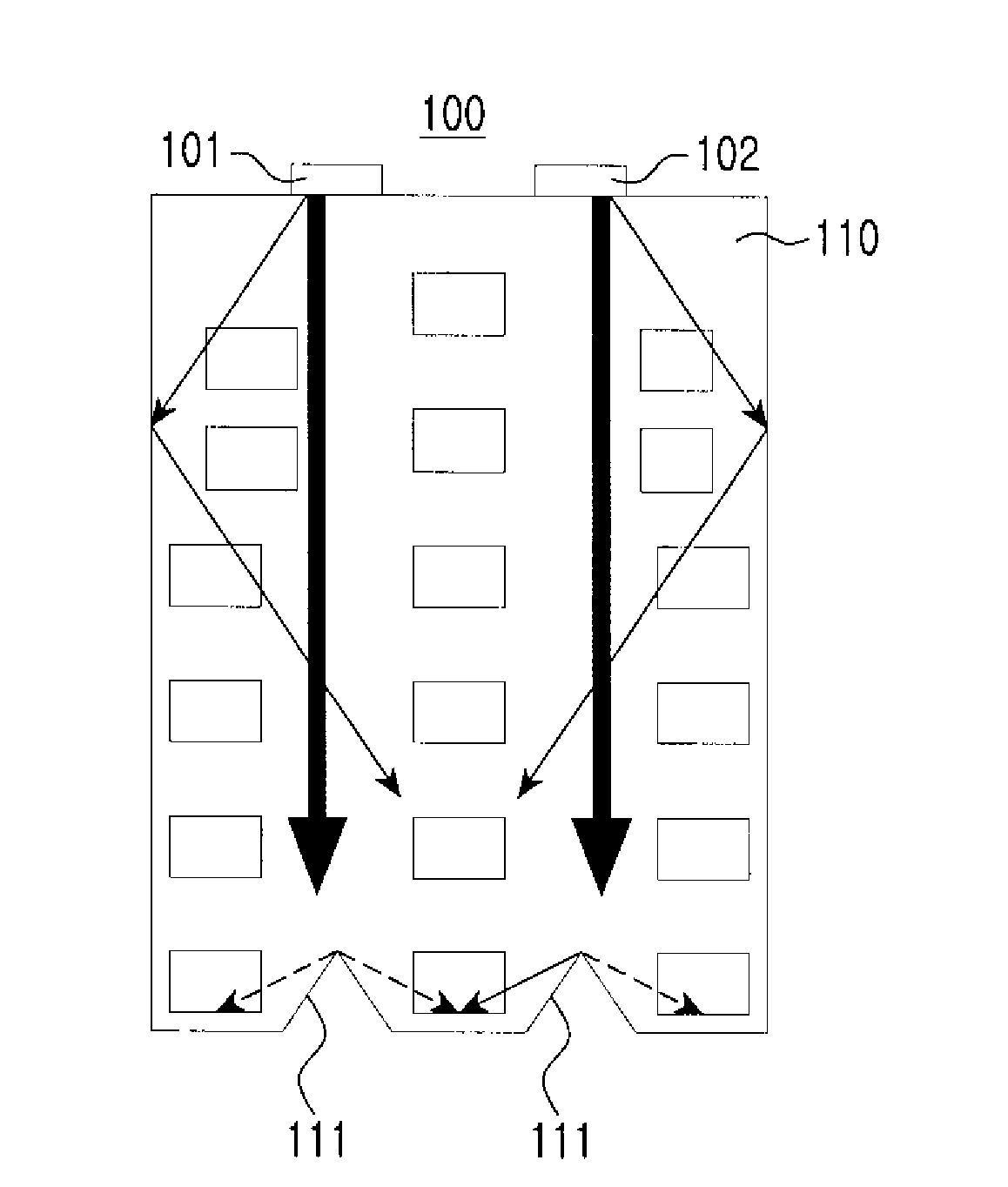
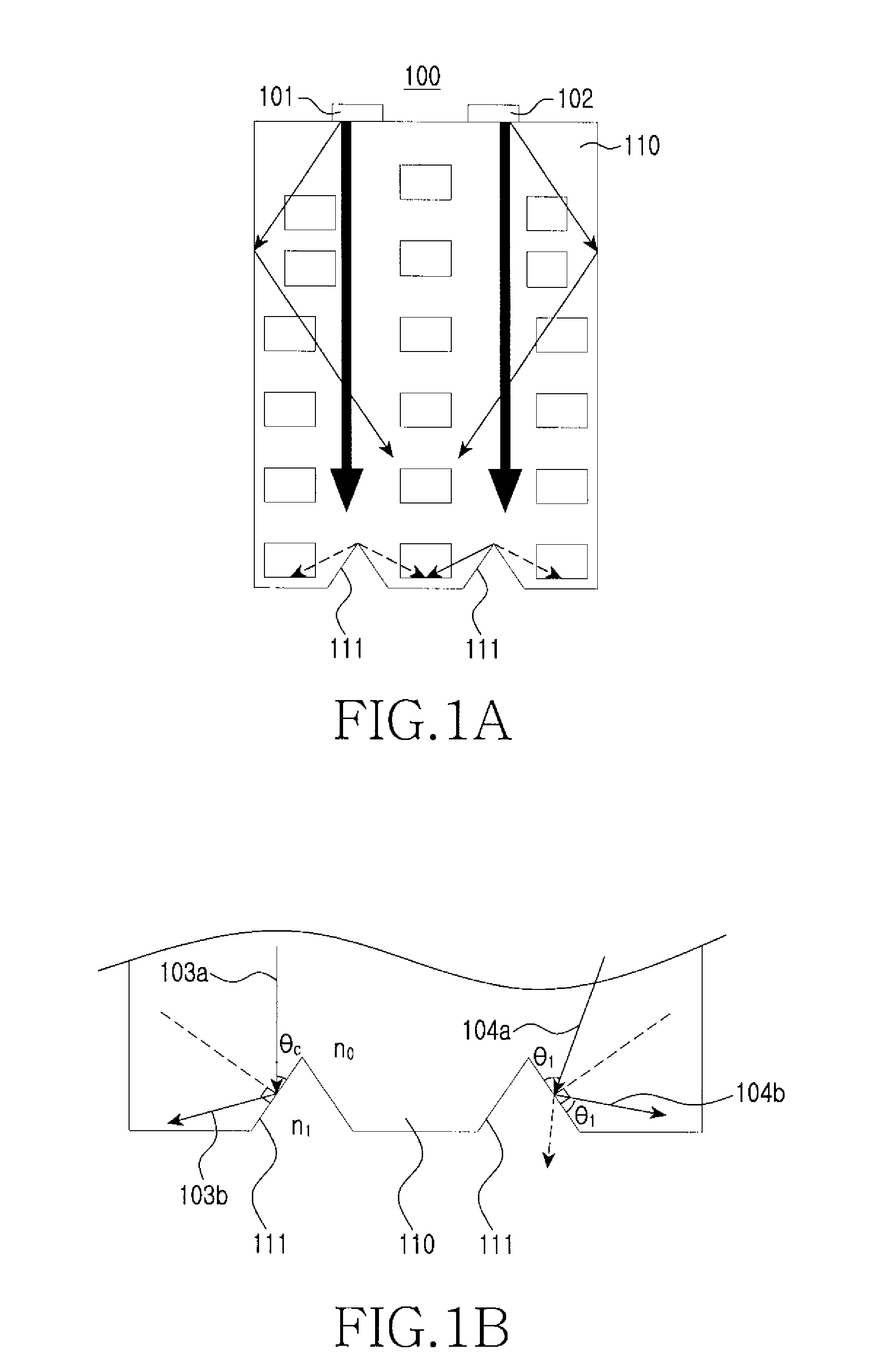
[0022]FIGS. 1a and 1b show a waveguide member according to the present invention. The waveguide member 100 includes a waveguide 110 for guiding light coupled to its inside, at least one recess 111 formed in a direction perpendicular to the direction in which light coupled to the inside of the waveguide 110 is guided so that incident light from the waveguide 110 is reflected to the waveguide 110, and light sources 101 and 102 for creating light.
[0023]The waveguide 110 guides light coupled to its inside so that the coupled light propagates from the first lateral surface of the waveguide 110 to its second lateral surface. As used herein, the first lateral surface of the waveguide 110 refers to one of its lateral surfaces to which light from the outside is coupled. The waveguide 110 may have any shape, such as a square or other geometrical shape. After being coupled to the inside of the waveguide 110, light undergoes total reflection at the interface between the waveguide 110 and its ex...
second embodiment
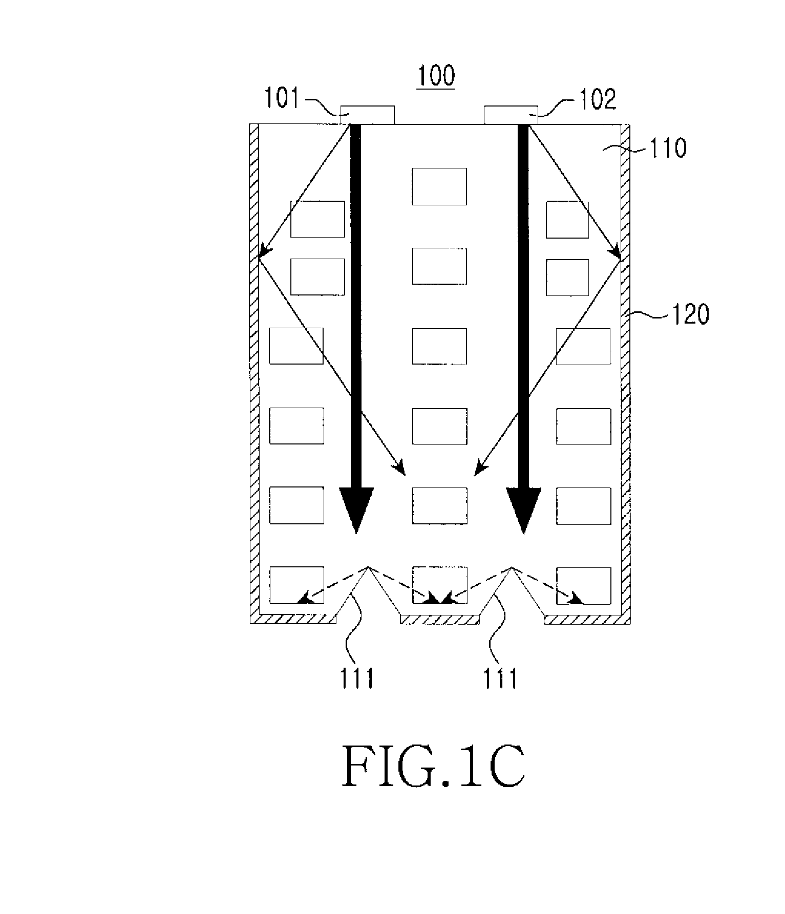
[0035]FIG. 2a shows a waveguide member according to the present invention. The waveguide member 200 includes a waveguide 210 for guiding light, which has been coupled to the inside via the first lateral surface, towards the second lateral surface, at least one light source 201 and 202 for outputting light to the first lateral surface of the waveguide 210, at least one recess 211 formed on the waveguide 210, and a light blocking layer 220 formed around the second lateral surface of the waveguide 210.
[0036]In the following description of the waveguide member 200 according to the second embodiment of the present invention, detailed descriptions of the same components and operations as in the case of the first embodiment of the present invention will be omitted for brevity.
[0037]The recess 211 may be formed along the second lateral surface inside the waveguide 210 so that light guided from the first lateral surface is reflected to the inside of the waveguide 210. As shown in FIG. 2b, th...
third embodiment
[0039]FIG. 3 shows a waveguide member according to the present invention. Referring to FIG. 3, the waveguide member 300 includes a waveguide 310 for guiding light, which has been coupled to the inside via the first lateral surface, to the second lateral surface, at least one recess 311 formed on the waveguide 310, a light blocking layer 320 formed along the second lateral surface of the waveguide 310, and light sources 301 and 302 for creating light to be coupled to the inside of the waveguide 310.
[0040]In the following description of the waveguide member 300 according to the third embodiment of the present invention, detailed descriptions of the same components and operations as in the case of the first and second embodiments of the present invention will be omitted for brevity.
[0041]The recess 311 may be locally formed on a part adjacent to the second lateral surface of the waveguide 310. Alternatively, the recess 311 may be a hole extending through the waveguide 310 or an indenta...
PUM
 Abstract
Description
Claims
Application Information
 - R&D
- Intellectual Property
- Life Sciences
- Materials
- Tech Scout
- Unparalleled Data Quality
- Higher Quality Content
- 60% Fewer Hallucinations
Browse by: Latest US Patents, China's latest patents, Technical Efficacy Thesaurus, Application Domain, Technology Topic, Popular Technical Reports.
© 2025 PatSnap. All rights reserved.Legal|Privacy policy|Modern Slavery Act Transparency Statement|Sitemap|About US| Contact US: help@patsnap.com


