Quick disconnect hose coupling
- Summary
- Abstract
- Description
- Claims
- Application Information
AI Technical Summary
Benefits of technology
Problems solved by technology
Method used
Image
Examples
Embodiment Construction
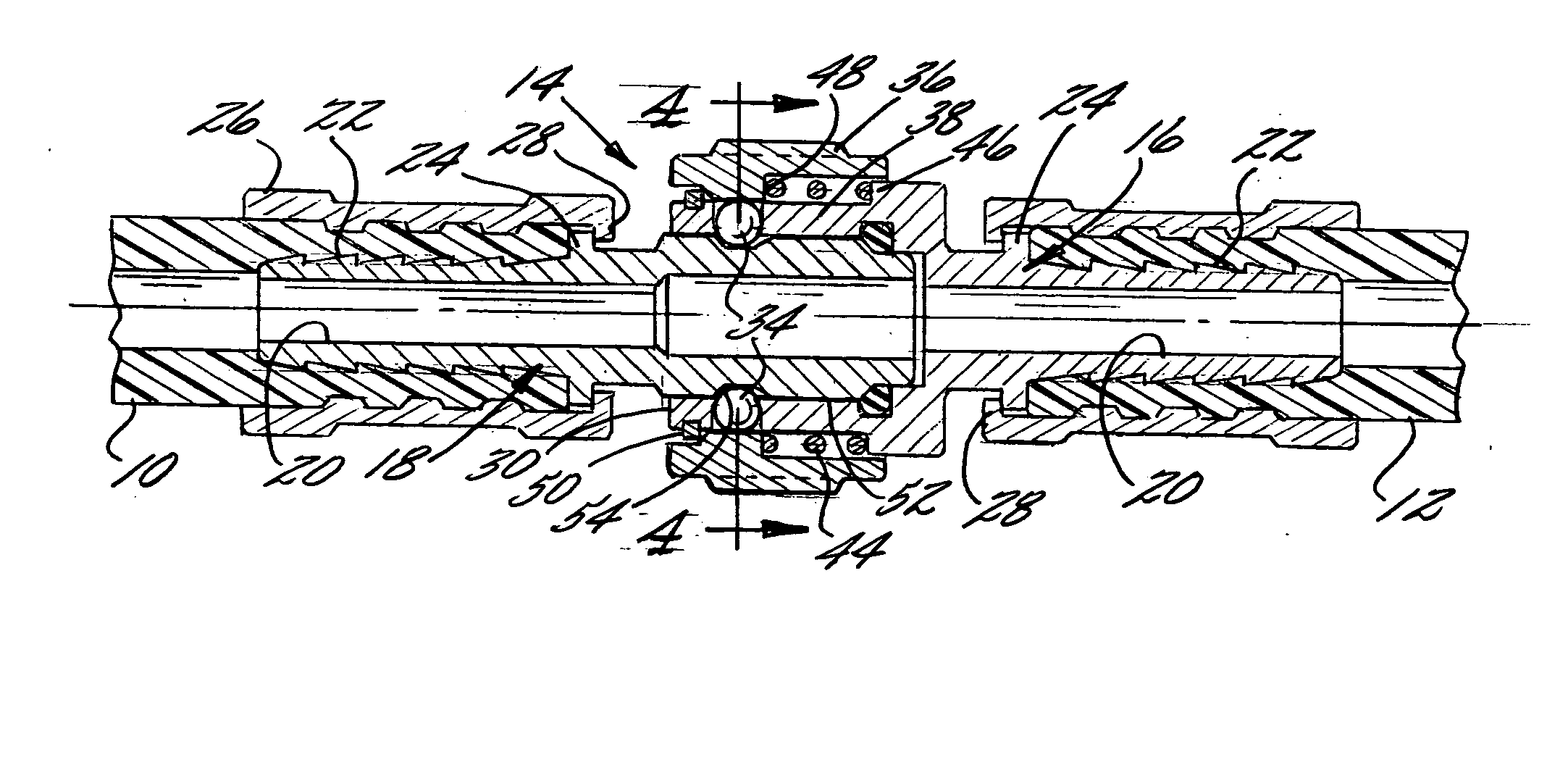
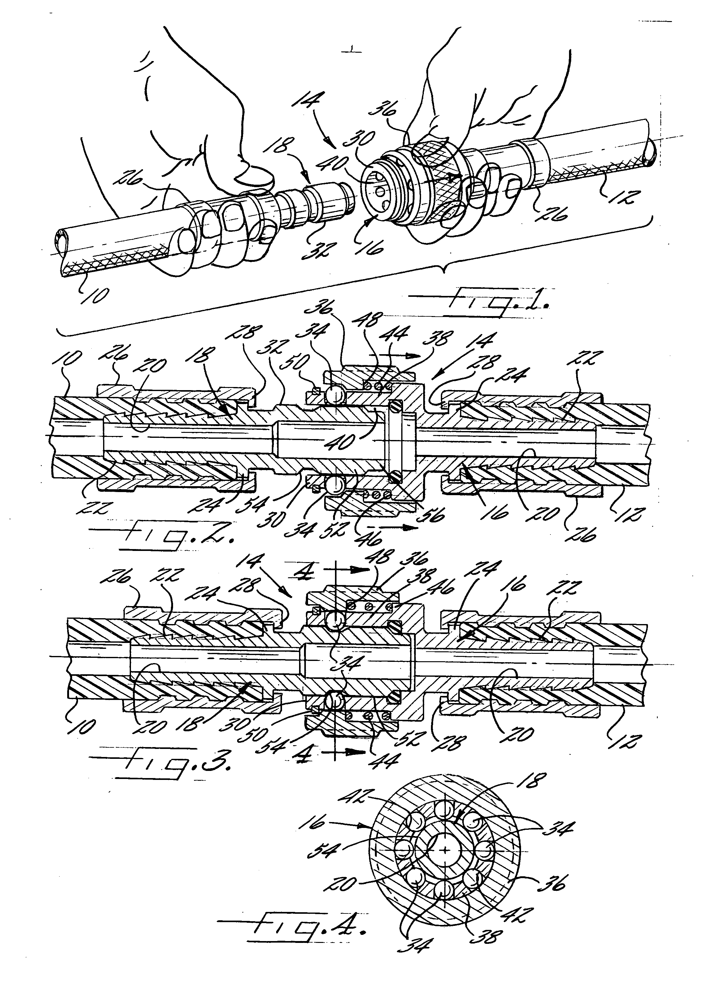
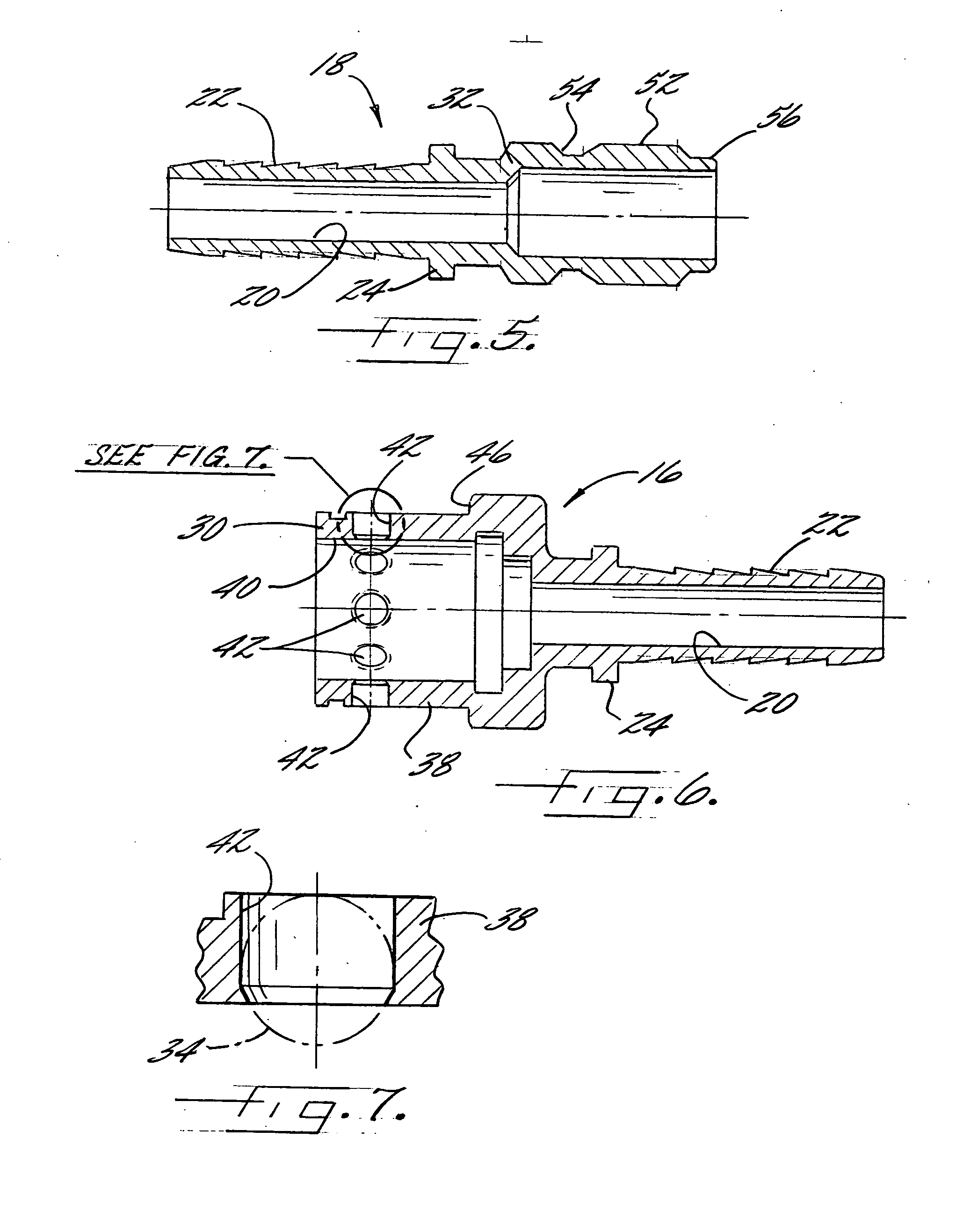
[0018] Referring now more particularly to the drawings, there is shown in FIG. 1 two illustrative lengths 10, 12 of hose having a quick disconnect coupling 14 in accordance with the invention. Each hose length 10, 12 in this case has a respective hose fitting 16, 18 at the ends of the hose to be connected (see FIGS. 2 and 3). Each of the fittings 16, 18, which preferably are made of metal, is formed with a liquid flow passageway 20 that communicates with the liquid flow passageway of the hose length 10, 12 to which it is connected. It will be understood that the opposite ends of the hose lengths 10, 12 also may be provided with appropriate fittings, either of a conventional type, or a quick disconnect type in accordance with the invention.
[0019] Each hose fitting 16, 18 in this case has a respective inwardly extending ribbed shank 22 that is forcefully positioned into the end of a hose length up to and against a radial locating flange 24 of the fitting as shown in FIGS. 2 and 3. An...
PUM
 Abstract
Description
Claims
Application Information
 - R&D
- Intellectual Property
- Life Sciences
- Materials
- Tech Scout
- Unparalleled Data Quality
- Higher Quality Content
- 60% Fewer Hallucinations
Browse by: Latest US Patents, China's latest patents, Technical Efficacy Thesaurus, Application Domain, Technology Topic, Popular Technical Reports.
© 2025 PatSnap. All rights reserved.Legal|Privacy policy|Modern Slavery Act Transparency Statement|Sitemap|About US| Contact US: help@patsnap.com


