Tip leakage flow directionality control

Active Publication Date: 2018-05-01
RAYTHEON TECH CORP
View PDF27 Cites 11 Cited by
  • Summary
  • Abstract
  • Description
  • Claims
  • Application Information

AI Technical Summary

Benefits of technology

[0004]A gas turbine engine according to an exemplary aspect of the present disclosure includes, among other things, an airfoil having a tip wall that joins outer spanwise ends of a suction sidewall and a pressure sidewall, a tip leakage control channel

Problems solved by technology

Due to various operational constraints, rotor blades and stator vanes are prone to leakage of compressed gases over their tips from a higher pressure surface to a lower pressure surface.
Several attempts have been

Method used


Image

  • Tip leakage flow directionality control
  • Tip leakage flow directionality control
  • Tip leakage flow directionality control

Examples


Embodiment Construction

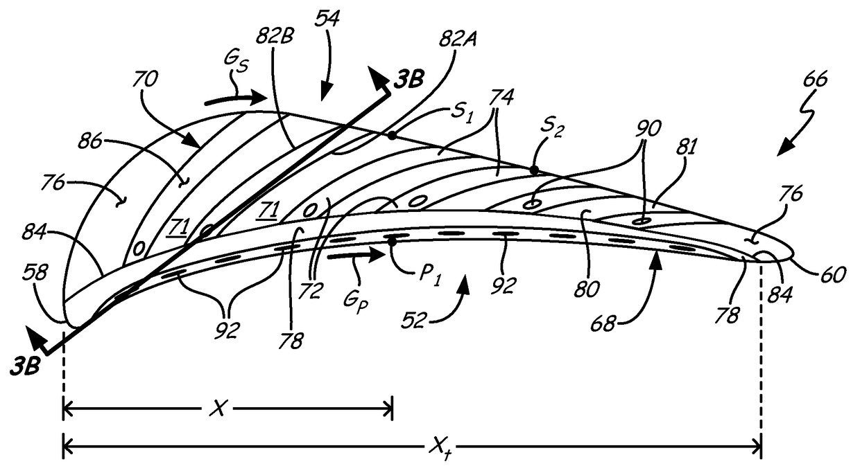
[0045]FIG. 1 is a cross-sectional view of gas turbine engine 10, including low spool 12, low pressure compressor (LPC) 14, low pressure turbine (LPT) 16, low pressure shaft 18, high spool 20, high pressure compressor (HPC) 22, high pressure turbine (HPT) 24, rotor blades 25, high pressure shaft 26, combustor 28, nacelle 30, propulsion fan 32, fan shaft 34, fan drive gear system 36, planetary gear 38, ring gear 40, sun gear 42, and fan exit guide vanes 44.

[0046]In the example two-spool, high bypass turbofan configuration, low spool 12 includes low pressure compressor (LPC) 14 driven by low pressure turbine (LPT) 16 via low pressure shaft 18. High spool 20 includes high pressure compressor (HPC) 22 driven by high pressure turbine (HPT) 24 via high pressure shaft 26. Low pressure shaft 18 and high pressure shaft 26 are mounted coaxially and rotate at different speeds. The power core also includes combustor 28 arranged in flow series between the compressor and turbine sections. HPT 24 a...


PUM


Abstract

A gas turbine engine according to an exemplary aspect of the present disclosure includes, among other things, an airfoil having a tip wall that joins outer spanwise ends of a suction sidewall and a pressure sidewall, a tip leakage control channel recessed into an outer surface of the tip wall, a tip leakage control vane integrally formed on the tip wall adjacent to the tip leakage control channel and an air seal radially outward of the tip wall and positioned to minimize leakage at the tip wall.

Description

CROSS-REFERENCE TO RELATED APPLICATIONS[0001]This application is a continuation-in-part of pending U.S. patent application Ser. No. 13 / 540,752, filed Jul. 3, 2012.BACKGROUND[0002]The described subject matter relates generally to turbine engines and more specifically to cooling turbine blades.[0003]Turbine engines provide efficient, reliable power for a wide range of applications in aviation, transportation and industrial power generation. Individual compressor and turbine section(s) may be subdivided into a number of stages, formed of alternating rows of rotor blade and stator vane airfoils. Due to various operational constraints, rotor blades and stator vanes are prone to leakage of compressed gases over their tips from a higher pressure surface to a lower pressure surface. Several attempts have been made to reduce these flows, but they cannot be completely eliminated due to clearance requirements over the airfoil tips which account for variations in both thermal and centrifugal gr...

Claims


Application Information

Patent Timeline
IPC IPC(8): F01D11/08F01D5/20F01D25/12F01D9/02
CPCF01D5/20F01D9/02F01D11/08F01D25/12Y02T50/673F05D2240/126F05D2240/55F05D2250/294F05D2220/32Y02T50/60
Inventor ZELESKY, MARK F.AGGARWALA, ANDREW S.
Owner RAYTHEON TECH CORP
Why Eureka
Try Eureka