Throttle valve positioning device

Inactive Publication Date: 2007-07-03
CONTINENTAL AUTOMOTIVE GMBH
View PDF41 Cites 12 Cited by
  • Summary
  • Abstract
  • Description
  • Claims
  • Application Information

AI Technical Summary

Benefits of technology

[0005]The object of the present invention consists in providing a t

Problems solved by technology

The avoidance of leakage air is made more difficult in particular in split housings having two housing shells, since the parting line of the two housing halves likewise lies in the region of the throttle valve, so that, on account of the very high vacuum produced in the region of the throttle valve, leakage air is drawn in in this region, which can scarcely b

Method used


Image

  • Throttle valve positioning device
  • Throttle valve positioning device
  • Throttle valve positioning device

Examples


Embodiment Construction

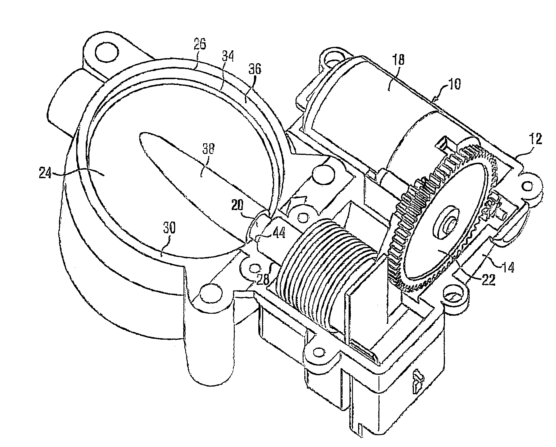
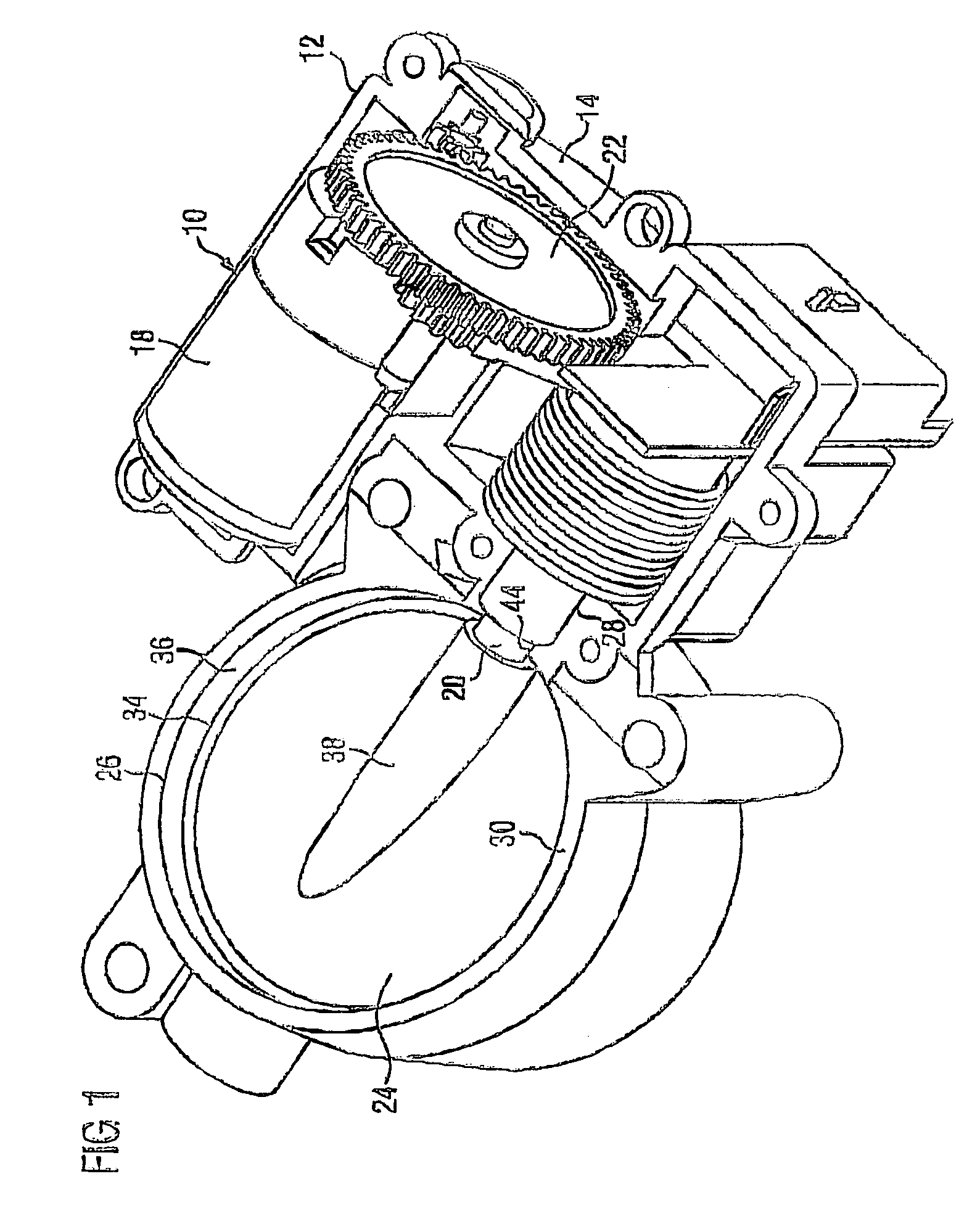
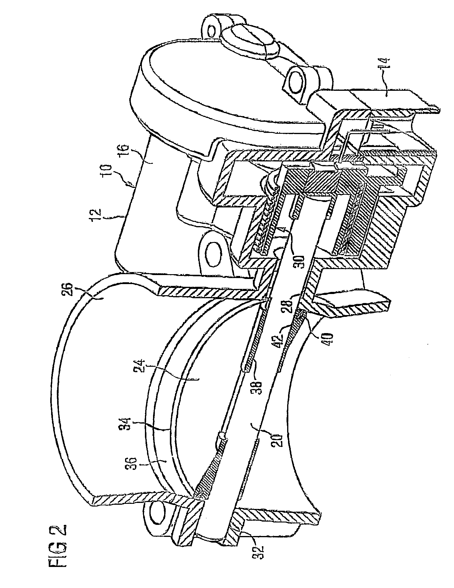
[0015]Shown in FIG. 1 is a throttle valve positioning device 10 which essentially comprises a housing 12 with a bottom housing half 14 and a top housing half 16, an actuator 18, a throttle valve shaft 20, which is coupled to the actuator 18 via gearing 22, and a throttle valve 24 which sits on the throttle valve shaft 20 and is pivotable in a throttle body 26 formed by the two housing halves 14, 16. In addition to a receptacle for the actuator 18 and the gearing 22, the housing also forms a bearing arrangement for the throttle valve shaft 20 at a first, drive-side bearing 28 in the parting line 30 between the two housing halves 14, 16 and at a second bearing 32 on the side opposite the drive in the throttle body 26. The second bearing 32 is at a distance from the parting line 30 between the housing halves and may also be designed as a closed bearing boss, whereas in FIG. 2 the bearing 32 is shown open outward.

[0016]The actuator 18 and the gearing 22 and also those regions of the two...


PUM


Abstract

A throttle valve positioning device is disclosed, The device has a housing with a bearing for a throttle valve shaft and a throttle valve support, within which a throttle valve pivots which sits on the throttle valve shaft, running into a shaft passage in the support. With the device, air leakage may be avoided, such that the periphery of the throttle valve is arranged at a separation from a passage for the throttle valve shaft in. the throttle valve support.

Description

BACKGROUND OF THE INVENTION[0001]The invention relates to a throttle valve positioning device having a housing which forms a bearing arrangement for a throttle valve shaft and comprises a throttle body in which a throttle valve is pivotable, said throttle valve sitting on the throttle valve shaft, which leads through the shaft passage into the throttle body, the housing being of split design, and the circumference of the throttle valve, at least on one side, lying next to the throttle valve shaft at a distance from a passage of the throttle valve shaft in the throttle body.[0002]In the hitherto known arrangements of throttle valves in the throttle body which sit centrally on the throttle valve shaft or in a slot in the throttle valve shaft, leakage air usually cannot be prevented from flowing past in the region between throttle valve shaft, throttle valve and throttle housing and also via the shaft apertures in the bearings. The avoidance of leakage air is made more difficult in par...

Claims


Application Information

Patent Timeline
IPC IPC(8): F02D11/10F02D9/08F02D9/10F16K1/22F16K1/226
CPCF02D9/1065F02D11/10F16K1/221F16K1/226
Inventor HANNEWALD, THOMASKOEHLER, STEFAN
Owner CONTINENTAL AUTOMOTIVE GMBH
Why Eureka
Try Eureka