Optical communication module using refraction plate for optical axis compensation, and manufacturing method of the same

a technology of optical communication module and refraction plate, which is applied in the direction of optics, instruments, optical light guides, etc., can solve the problems of increasing optical loss, positional misalignment at the time of fixation, and extremely narrow optical axial alignment tolerance in the case of optical coupling and fixation of optical components, so as to reduce the number of components, improve the temperature stability of the optical communication module, and minimize optical loss

Inactive Publication Date: 2010-04-06
NEC CORP
View PDF20 Cites 6 Cited by
  • Summary
  • Abstract
  • Description
  • Claims
  • Application Information

AI Technical Summary

Benefits of technology

[0012]By this invention, it is possible to minimize optical loss generated by a positional misalignment at the time of fixing the first and second optical components, and the lens in fabricating the module. And then, an optical coupling state between the first optical component and second optical component improves.
[0013]According to this invention, since a refraction plate which is made of inorganic material whose refractive index varies little with temperature, the optical coupling state is not sensitive to the variation of environmental temperature. And then, temperature stability of the optical communication module becomes excellent.
[0014]According to this invention, since an optical communication module is made by a single lens system, the number of components is decreased in comparison with a dual lens system. And then, a high level of integration is realized easily.

Problems solved by technology

However, the optical axial alignment tolerance in the case of optical coupling and fixation of optical components is extremely narrow, because the spot size is small (nearly 1 to several μm).
Often, when a plurality of optical components is fixed for being coupled optically, a positional misalignment can arise at the time of the fixation.
When the positional misalignment arises, optical loss increases, and then, many characteristics of the optical module which is constructed of the coupled optical components deteriorate.
However, as shown in the Japanese Patent Laid-Open No. 2004-272143, in the method of optical axis compensation by inserting a parallel plate in a focal point side of a dual lens system, because the focal length of a lens for a dual lens system is generally short, a space for inserting the parallel plate is limited.
Therefore, integration of an optical module is difficult.
Therefore, the usage of the module is difficult.

Method used


Image

  • Optical communication module using refraction plate for optical axis compensation, and manufacturing method of the same
  • Optical communication module using refraction plate for optical axis compensation, and manufacturing method of the same
  • Optical communication module using refraction plate for optical axis compensation, and manufacturing method of the same

Examples


embodiment 1

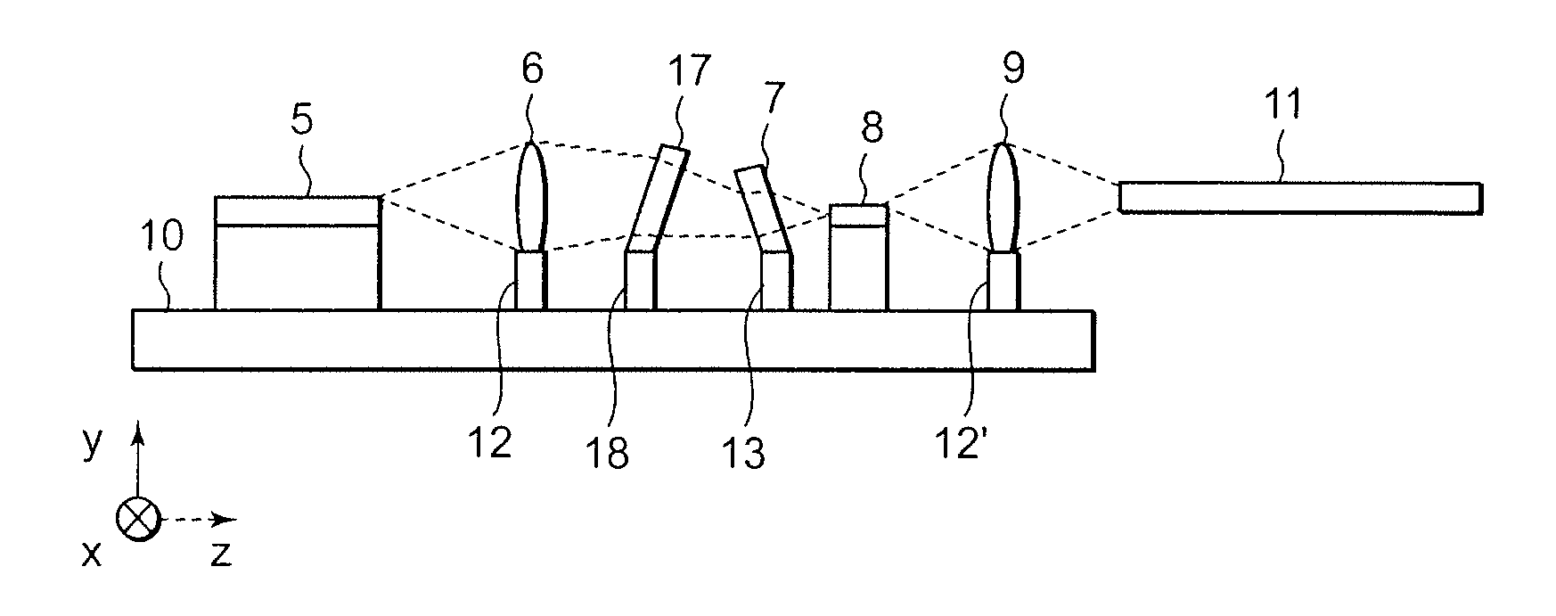
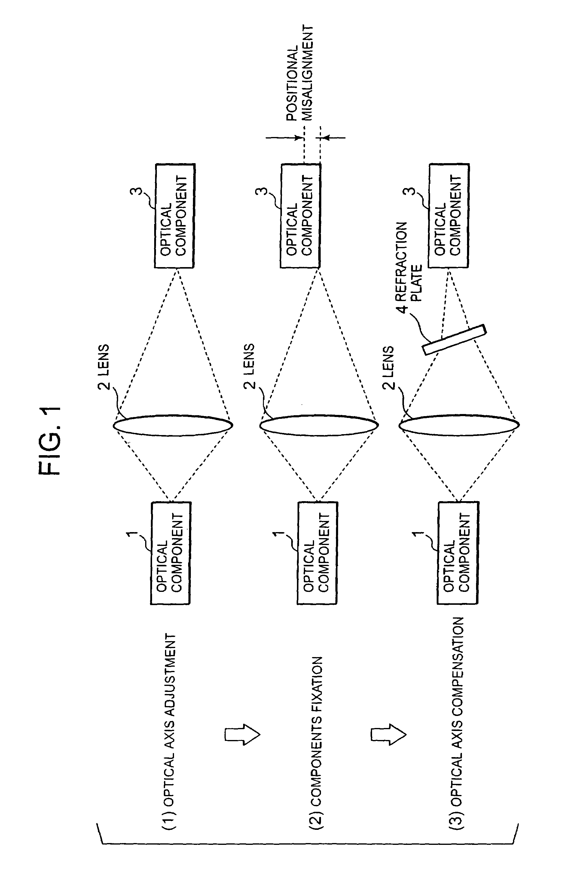
[0024]Often, when a plurality of optical components is fixed in an optical communication module where components are being coupled optically, a positional misalignment arises. And when the positional misalignment arises, optical loss increases, and then, many characteristics of the optical communication module which is constructed of the coupled optical components deteriorate.

[0025]This embodiment is characterized by having the construction which makes it possible to compensate a positional misalignment generated at the time of fixing the optical components. This is realized by providing a mechanism of compensating the positional misalignment in an optical communication module. This embodiment adopts a single lens system in order to save space for placing the means for positional misalignment compensation. Furthermore, this embodiment saves further space by using an optical film, which has originally a function different from positional misalignment compensation, as the means for fu...

embodiment 2

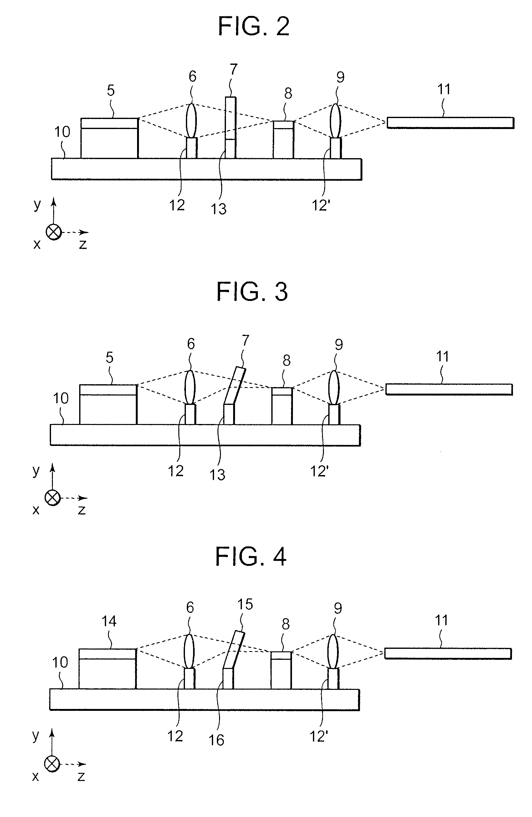
[0039]An optical communication module of this embodiment is explained below using attached drawings. First, the internal construction of the optical communication module of this embodiment is explained using FIG. 4. FIG. 4 is a sectional view of the internal construction of the optical communication module of this embodiment. As shown in FIG. 4, a PLC resonator 14, a first lens 6 fixed to a lens holder 12, a band pass filter (BPF) 15 fixed to a BPF holder 16, an optical amplifier 8, and a second lens 9 fixed to a lens holder 12′ are mounted on a carrier 10. Emitted light from the second lens 9 is made to be received within an optical fiber 11. Here, the band pass filter (BPF) 15 is for removing a periodic aliasing-resonance frequency which the PLC resonator 14 has.

[0040]Next, the fabricating method of this embodiment is explained using FIG. 4. First, as shown in FIG. 4, the optical amplifier 8 is implemented on the carrier 10. Then, as making the implemented optical amplifier 8 emit...

embodiment 3

[0048]This embodiment is a modified example of the first embodiment. FIG. 5 is a sectional view of the internal construction of an optical communication module of this embodiment. Only the characteristic portions of this embodiment are explained below using FIG. 5. As shown in FIG. 5, this embodiment is characterized by further performing optical axis compensation to the optical fiber 11, which is an optical component constituting the optical communication module, in addition to the first embodiment. Regarding the optical amplifier 8 shown in FIG. 5, there are some types which emit radiant light whose wavelengths are outside the amplifying band of the optical amplifier 8. So, in the case of using such the optical amplifier 8, it is necessary to cut the wavelengths out of the amplifying band. Then, generally, the band pass filter (BPF) 15 is inserted in a subsequent stage of the optical amplifier 8. In this embodiment, the coupling efficiency of the optical amplifier 8 and optical fi...


PUM


Abstract

An optical communication module is fabricated to include a refraction plate made of an inorganic material whose refractive index varies little with temperature. The refraction plate is inserted in the optical path to perform optical axis compensation in a single lens system with long focal length.

Description

BACKGROUND OF THE INVENTION[0001]1. Field of the Invention[0002]The present invention relates to an optical communication module using a refraction plate for optical axis compensation, and its manufacturing method.[0003]2. Description of the Related Art[0004]In recent years, multi-functionalization of an optical module aimed at space saving has been advancing. Along with it, the necessity of integrating a plurality of optical components into one optical module arises. However, the optical axial alignment tolerance in the case of optical coupling and fixation of optical components is extremely narrow, because the spot size is small (nearly 1 to several μm).[0005]Often, when a plurality of optical components is fixed for being coupled optically, a positional misalignment can arise at the time of the fixation. When the positional misalignment arises, optical loss increases, and then, many characteristics of the optical module which is constructed of the coupled optical components deter...

Claims


Application Information

Patent Timeline
Patent Type & Authority Patents(United States)
IPC IPC(8): G02B6/32G02B6/00
CPCG02B6/422G02B6/4204
Inventor KANEKO, TAROKANEMOTO, MITSUNORI
Owner NEC CORP
Why Eureka
Try Eureka