Flexing chip heatsink

a heatsink and flexible technology, applied in the direction of cooling/ventilation/heating modification, semiconductor/solid-state device details, semiconductor devices, etc., can solve the problem of heatsink “breakage”, and achieve the effect of adequate heat dissipation, small footprint and high thermal heat conductivity

Inactive Publication Date: 2007-06-14
IBM CORP
View PDF16 Cites 10 Cited by
  • Summary
  • Abstract
  • Description
  • Claims
  • Application Information

AI Technical Summary

Benefits of technology

[0005] The present invention solves this problem by providing a flexible radiating heatsink that will elastically deform without breaking or disconnecting from its IC chip in response to an external contact, and then return to its original size, shape and position without transmitting the external force to the electronic component(s) it is cooling. This is accomplished by using an array of connected flexible joints providing a “folded configuration” instead of a rigid extrusion for the heatsink skeletal construction. Metals or other materials having a high thermal heat conductivity (such as for example copper or aluminum) are preferably constructed into flexible corrugated thin sheets which are connected together to form a “small footprint” / “tall” heatsink configuration. Use of such a configuration allows the heatsink structure to absorb stress by resiliently flexing and then returning to its original shape without breaking in reaction to a contact, instead of transmitting the contact force to the connection between the heatsink and its IC / PCB and breaking off in response to a shearing stress.
[0006] It is therefore an object of the present invention to overcome the disadvantages of the prior art by providing a method, apparatus and system using a flexible radiating heatsink for cooling electronic components on integrated circuit chips that is constructed with an array of connected flexible joints which elastically deform without breaking or disconnecting from the chip in response to an external contact force and then return to an original size, shape and position without transmitting the external force to the cooled component(s).
[0007] It is another object of the present invention to overcome the disadvantages of the prior art by providing a flexible radiating heatsink that is constructed of material(s) capable of assuming a configuration having sufficient flexibility to remain within plastic limits during elastic deformation so as to resiliently absorb stress instead of breaking in reaction to a contact force or transmitting the force to the cooled electronic component(s).
[0008] It is another object of the present invention to overcome the disadvantages of the prior art by providing a flexible radiating heatsink that is constructed with corrugated thin metal sheets joined together into an array configuration having a limited area in contact with the cooled component(s) and an extended dimension providing a sufficient surface area exposed to ambient air to allow adequate heat dissipation to occur.

Problems solved by technology

However, even though such a “small footprint” / “tall” heatsink configuration provides adequate cooling for high density IC microchips, its extended height causes problems (particularly during manufacturing) by increasing the tendency of the heatsink to “break off” (or disconnect) from its IC and printed circuit board (PCB) in response to accidental contact, due to the increased rotational moment created by its extended vertical profile.

Method used


Image

  • Flexing chip heatsink
  • Flexing chip heatsink
  • Flexing chip heatsink

Examples


Embodiment Construction

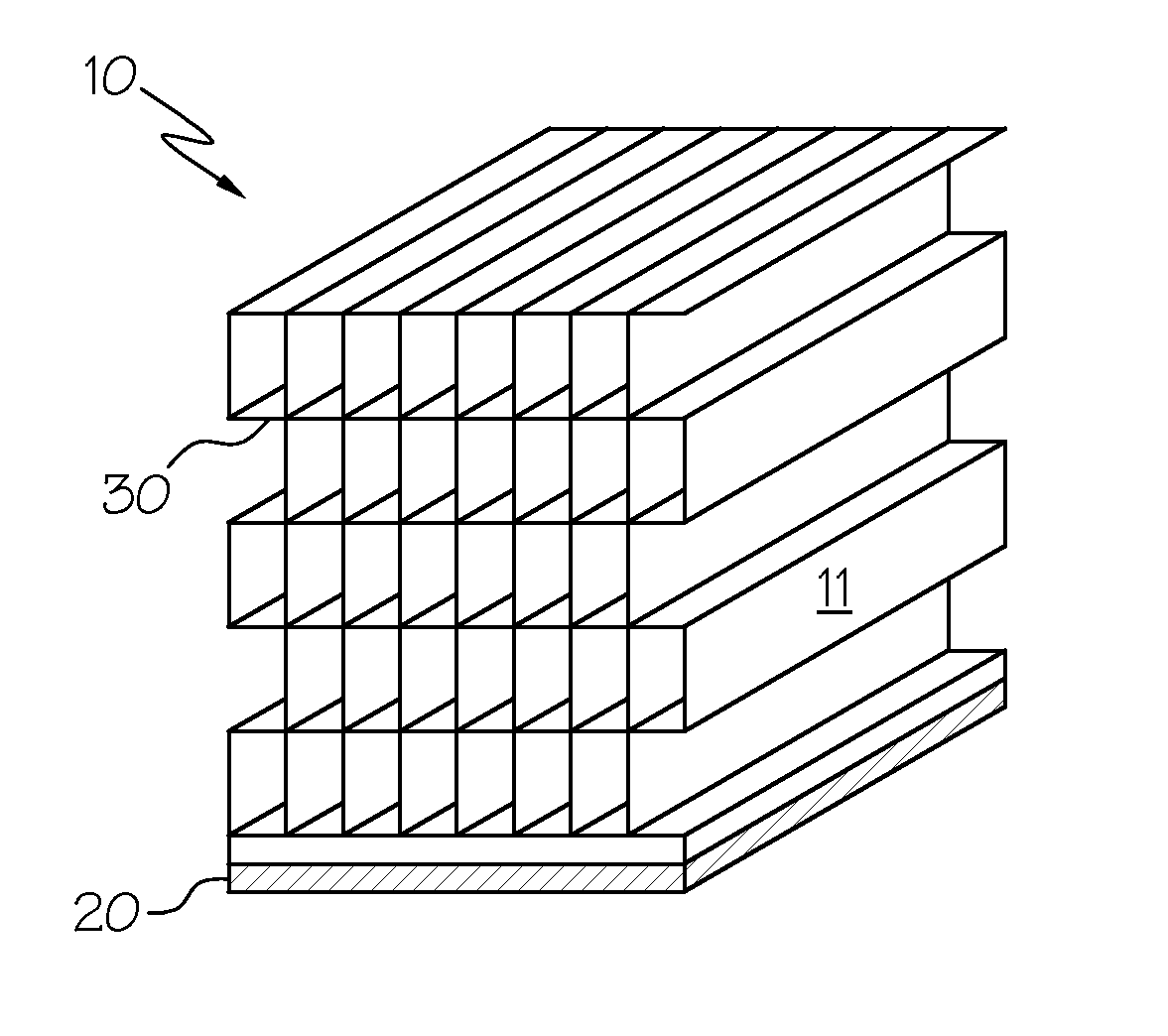
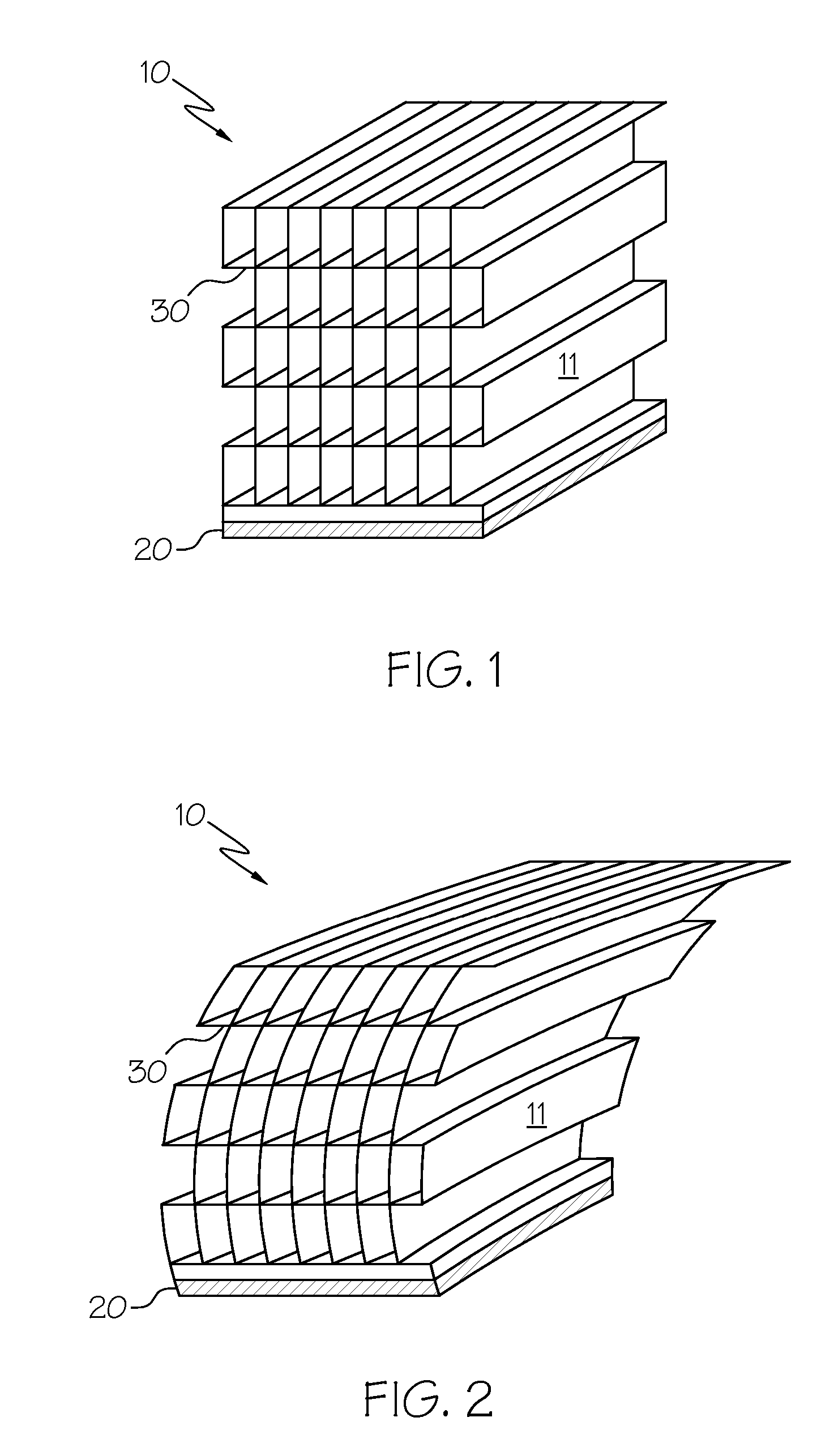
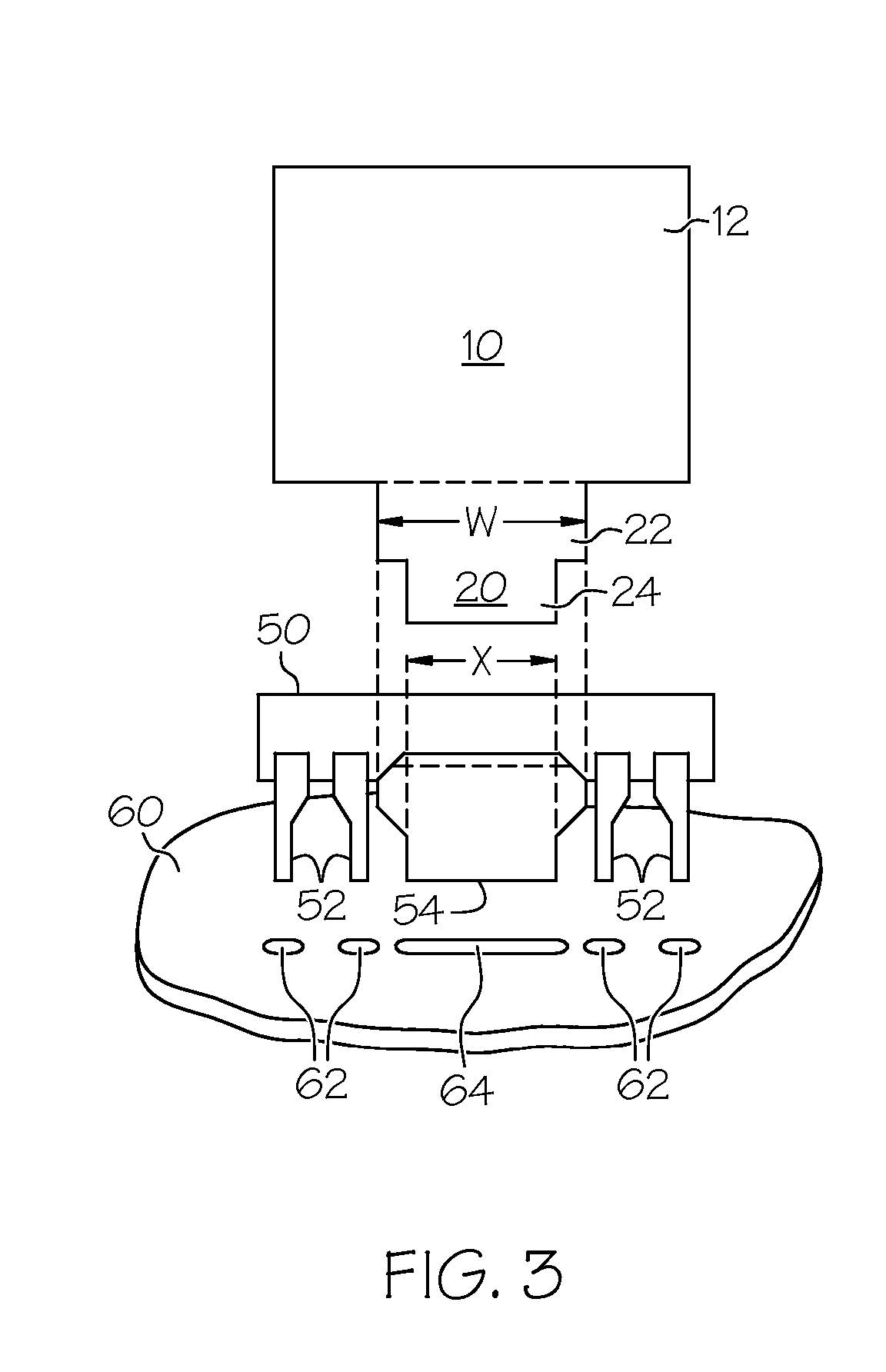
[0016] Integrated circuits (ICs) may be produced in a variety of packages. A common one is the dual-in-line package (or DIP) as shown in the prior art configurations of FIG. 3&FIG. 4, in which the IC chip 50 is encased in a rectangular box of dielectric material. Numerous metallic terminals or pins 52 are located along sides of the DIP package. Several of the pins 52 are connected to the IC chip 50 inside the box, thereby permitting electrical connections to be made to the circuit(s) located on the chip. Other pins 54 (usually those closest to the centrally located chip) are in physical contact with the metallic ground plane on the bottom of the chip 50 and are used to conduct heat from the chip to the external environment. A heat dissipator (or “heatsink”) 10 may be attached so as to contact the heat-conducting pins 54 and thereby conduct heat away from the IC chip 50. The heatsink 10 is usually attached prior to mounting the IC chip 50 in a printed circuit board (PCB) (not shown) ...


PUM


Abstract

A method, apparatus and system are disclosed for using a flexible radiating heatsink for cooling electronic components on integrated circuit chips. The heatsink elastically deforms without breaking or disconnecting in response to an external contact and then returns to its original size, shape and position, without transmitting the external force to the electronic component(s) it is cooling.

Description

TECHNICAL FIELD [0001] This invention relates to heat dissipators (or “heatsinks”) used for cooling electronic components, and in particular to a heat dissipator used with integrated circuits (“ICs”). More particularly, this invention relates to the field of radiating heatsinks, and specifically to a flexible metal radiating heatsink for cooling electronic components on IC chips, that elastically deforms without breaking or disconnecting in response to an external contact and then returns to its original size, shape and position, without transmitting the external force to the electronic component(s) it is cooling. BACKGROUND [0002] Miniaturization of electronic devices is made possible today largely through the use of integrated circuits (“ICs”), in which a large number of electronic components such as various types of transistors, capacitors, resistors, amplifiers, logic circuits and others are manufactured, located, and electrically connected and combined together into circuits on...

Claims


Application Information

Patent Timeline
Patent Type & Authority Applications(United States)
IPC IPC(8): H05K7/20
CPCH01L23/3672H01L2924/0002H01L2924/00
Inventor LOEBACH, BETH FRAYNEARMSTRONG, ADAM IANWILHITE, DALE W.
Owner IBM CORP
Why Eureka
Try Eureka