
Cpp magnetoresistive head

a magnetoresistive head and head technology, applied in the field of magnetic read head, can solve the problem that the proportion of the magnetoresistive film tends to generate heat, and achieve the effects of high heat conductivity, low linear expansion coefficient, and high heat conductivity layer

Active Publication Date: 2010-02-25
WESTERN DIGITAL TECH INC
View PDF10 Cites 8 Cited by
  • Summary
  • Abstract
  • Description
  • Claims
  • Application Information

AI Technical Summary

Benefits of technology

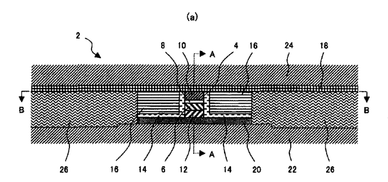
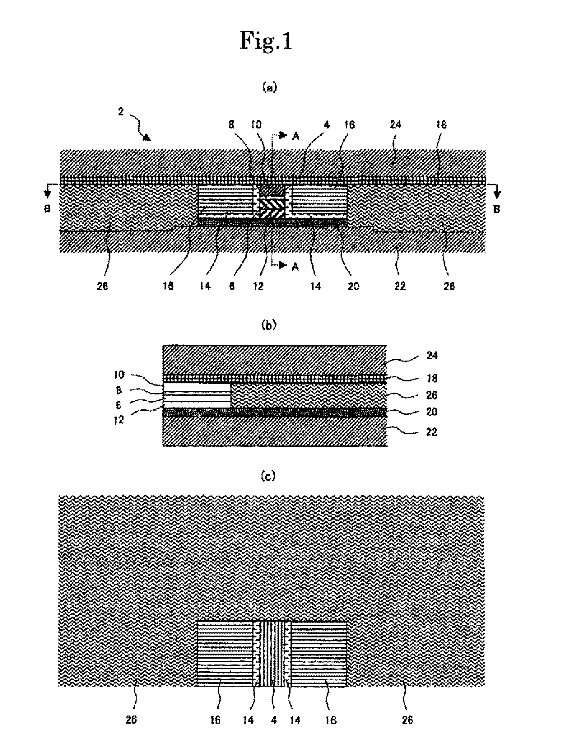
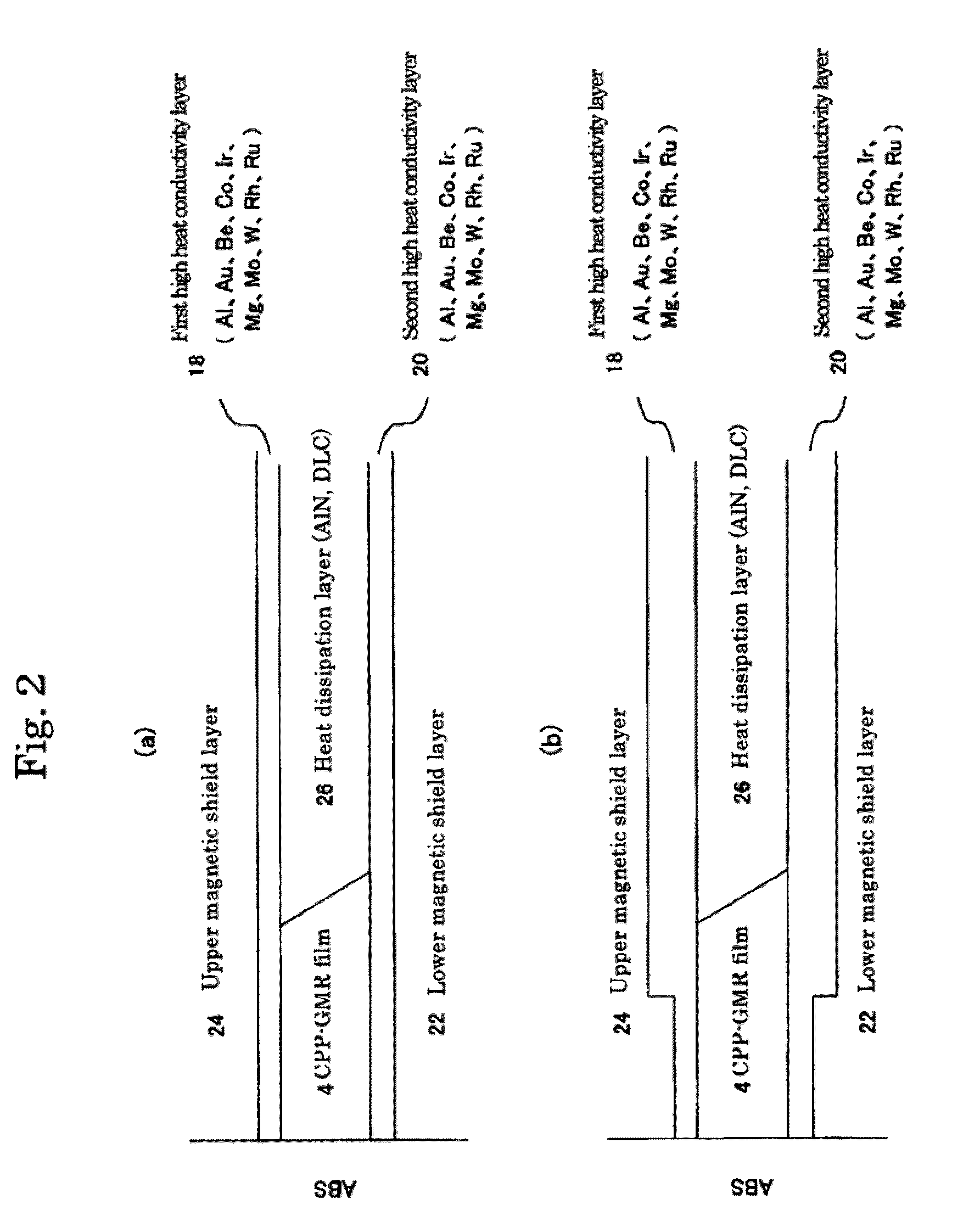
[0008]According to one embodiment, a CPP magnetoresistive head includes a magnetoresistive film comprising a free layer above a non-magnetic intermediate layer and a fixed layer below the non-magnetic intermediate layer, wherein the magnetoresistive film is between a lower magnetic shield layer and an upper magnetic shield layer. The CPP magnetoresistive head also includes a domain control film disposed by way of an insulating film on each side of the magnetoresistive film, wherein a sense current flows through the magnetoresistive film between the upper magnetic shield layer and the lower magnetic shield layer, and a high heat conductivity layer disposed between the upper magnetic shield layer and the magnetoresistive layer or between the lower magnetic shield layer and the magnetoresistive film, and a heat dissipation layer having a high heat conductivity and a low linear expansion coefficient, the heat dissipation layer being disposed at the back in a device height direction of the magnetoresistive film and on each side of the domain control film, wherein the heat dissipation layer is disposed between the high heat conductivity layer and the upper magnetic shield layer or the lower magnetic shield layer.

Problems solved by technology

The CPP structure magnetoresistive head generally includes a problem that the portion of the magnetoresistive film tends to generate heat more than that in a CIP (current into the plane) structure magnetoresistive head.

Method used


Image

  • Cpp magnetoresistive head
  • Cpp magnetoresistive head
  • Cpp magnetoresistive head

Examples


Embodiment Construction

[0021]The following description is made for the purpose of illustrating the general principles of the present invention and is not meant to limit the inventive concepts claimed herein. Further, particular features described herein can be used in combination with other described features in each of the various possible combinations and permutations.

[0022]Unless otherwise specifically defined herein, all terms are to be given their broadest possible interpretation including meanings implied from the specification as well as meanings understood by those skilled in the art and / or as defined in dictionaries, treatises, etc.

[0023]It must also be noted that, as used in the specification and the appended claims, the singular forms “a,”“an” and “the” include plural referents unless otherwise specified.

[0024]The following description discloses several preferred embodiments of disk-based storage systems and / or related systems and methods, as well as operation and / or component parts thereof.

[00...


PUM

PropertyMeasurementUnit
temperatureaaaaaaaaaa

Abstract

According to one embodiment, a CPP magnetoresistive head includes a magnetoresistive film comprising a free layer above a non-magnetic intermediate layer and a fixed layer below the non-magnetic intermediate layer, wherein the magnetoresistive film is between a lower magnetic shield layer and an upper magnetic shield layer. The CPP magnetoresistive head also includes a domain control film on each side of the magnetoresistive film, wherein a sense current flows through the magnetoresistive film between the upper magnetic shield layer and the lower magnetic shield layer. The CPP magnetoresistive head also includes a high heat conductivity layer, and a heat dissipation layer having a high heat conductivity and a low linear expansion coefficient, the heat dissipation layer being disposed at the back in a device height direction of the magnetoresistive film and on each side of the domain control film.

Description

RELATED APPLICATIONS[0001]The present application claims the priority of a Japanese patent application filed Aug. 22, 2008 under application number 2008-214262, which is incorporated herein by reference.FIELD OF THE INVENTION[0002]The present invention concerns a magnetic read head including a magnetoresistive film for reading magnetically recorded information, and particularly relates to a magnetoresistive head of a Current Perpendicular to Plane (CPP) structure for flowing a detection current to the film plane in a perpendicular direction.BACKGROUND OF THE INVENTION[0003]A magnetic recording device, for example, a hard disk drive, has gradually been expected to provide more storage capacity as the recent trend of the information society has demanded it. One way to increase the storage capacity of magnetic recording devices is to increase the recording density per unit area of the magnetic recording device, and improvement in techniques for increasing the sensitivity of a read devi...

Claims


Application Information

Patent Timeline
Patent Type & Authority Applications(United States)
IPC IPC(8): G11B5/127
CPCB82Y10/00B82Y25/00G11B2005/3996G11B5/3912G11B5/3909
Inventor OSUGI, MASAHIROOHTSU, TAKAYOSHIFUJITA, SHIGEOWATANABE, KATSUROKATAOKA, KOJI
Owner WESTERN DIGITAL TECH INC
Learn More