
Adjustable clip advance
a conveyor and clip technology, applied in the field of adjustable clip advance, can solve the problems of impeded or prevented engagement, time-consuming and thus cost-intensive clip conveyor apparatuses known in practice, and suffer from further disadvantages, and achieve the effect of simple adjustment and simple structur
- Summary
- Abstract
- Description
- Claims
- Application Information
AI Technical Summary
Benefits of technology
Problems solved by technology
Method used
Image

Examples
Embodiment Construction
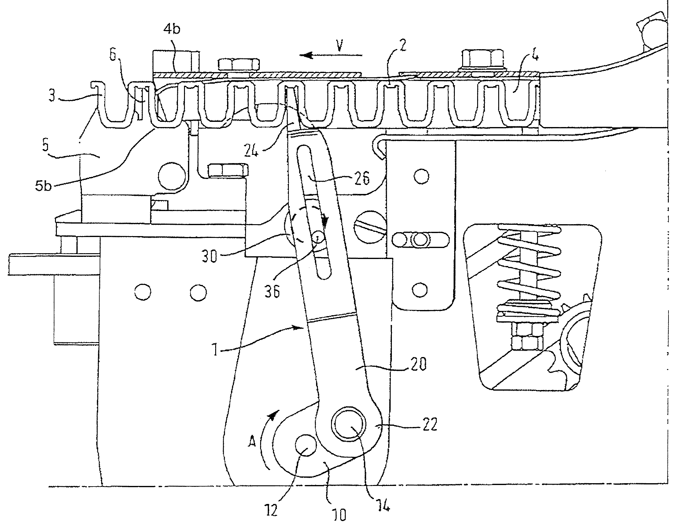
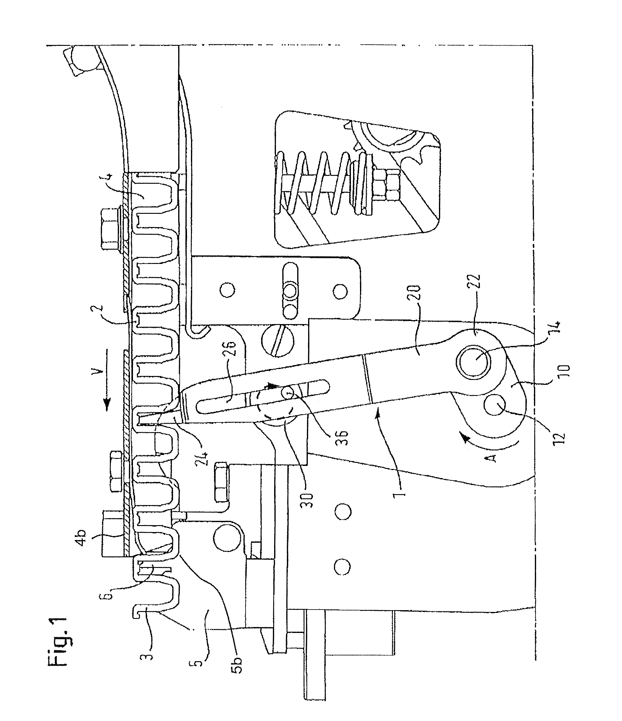
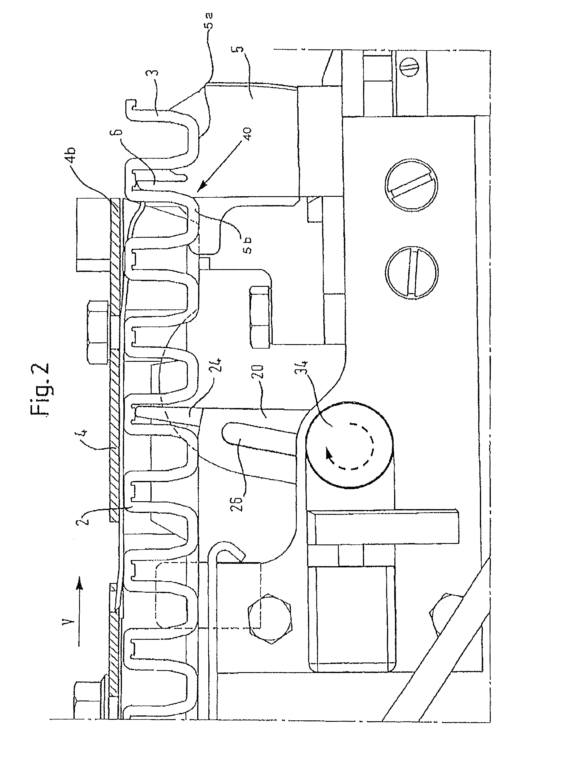
[0031]The embodiment described hereinafter of a clip conveyor apparatus according to the invention is used in for example sausage clipping machines. As can be seen from FIG. 1 the clip conveyor apparatus 1 includes a drive unit 10, an advance or transport element 20, an adjusting device 30 and a retaining device 40.
[0032]The drive unit 10, which in the illustrated embodiment has an eccentric as the drive element, is disposed beneath the horizontally extending clip line 2 that is guided in a clip guide 4. The eccentric is mounted on a rotatably mounted drive shaft 12. The eccentric is arranged in rotationally and axially fixedly mounted relationship in such a way that its eccentric pin or journal describes a circle extending in the plane of FIG. 1. The eccentric can be caused to rotate for example by a belt or chain drive (not further shown), which is driven by the main machine drive or by the main machine shaft. It is equally possible for the drive of the eccentric to be driven by a...
PUM
 Abstract
Description
Claims
Application Information