Vehicle body lower structure

a technology for vehicles and lower structures, applied in vehicle arrangements, roofs, transportation and packaging, etc., can solve problems such as sacrificing interior space, achieve the effects of suppressing the entry of the pillar into the interior space of the vehicle, suppressing the deformation of the vehicle body in a side collision, and suppressing the deformation of the vehicle body

a technology for vehicles and lower structures, applied in vehicle arrangements, roofs, transportation and packaging, etc., can solve problems such as sacrificing interior space, achieve the effects of suppressing the entry of the pillar into the interior space of the vehicle, suppressing the deformation of the vehicle body in a side collision, and suppressing the deformation of the vehicle body

US7963588B2Active Publication Date: 2011-06-21TOYOTA JIDOSHA KK

Image

  • Vehicle body lower structure
  • Vehicle body lower structure
  • Vehicle body lower structure

Examples


Embodiment Construction

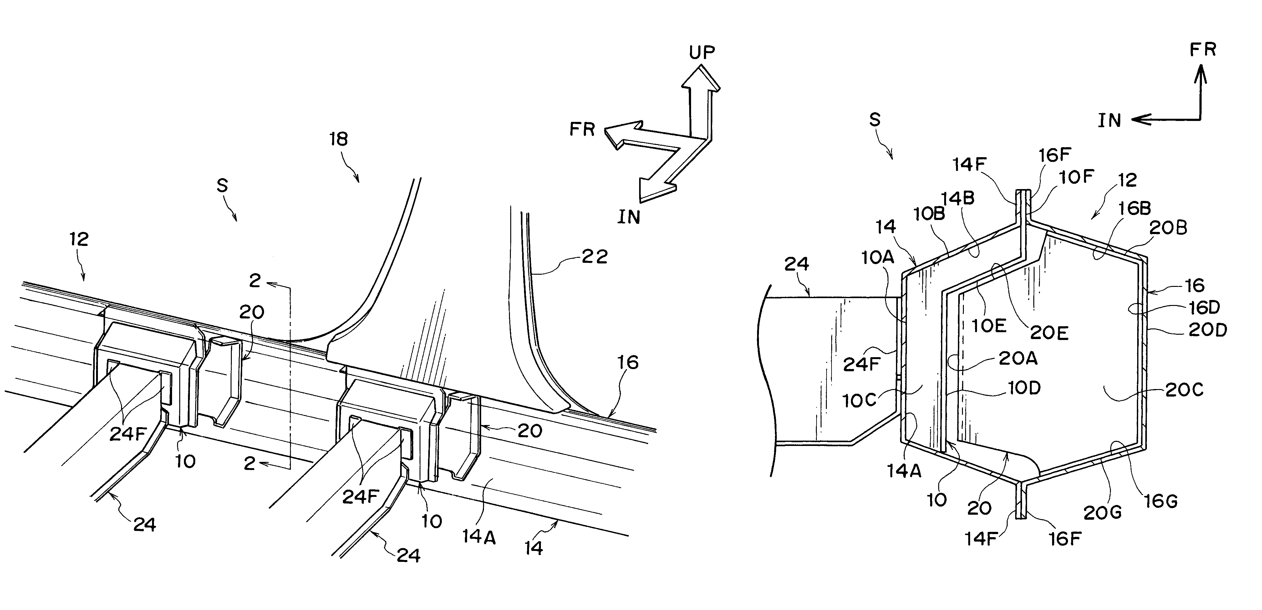
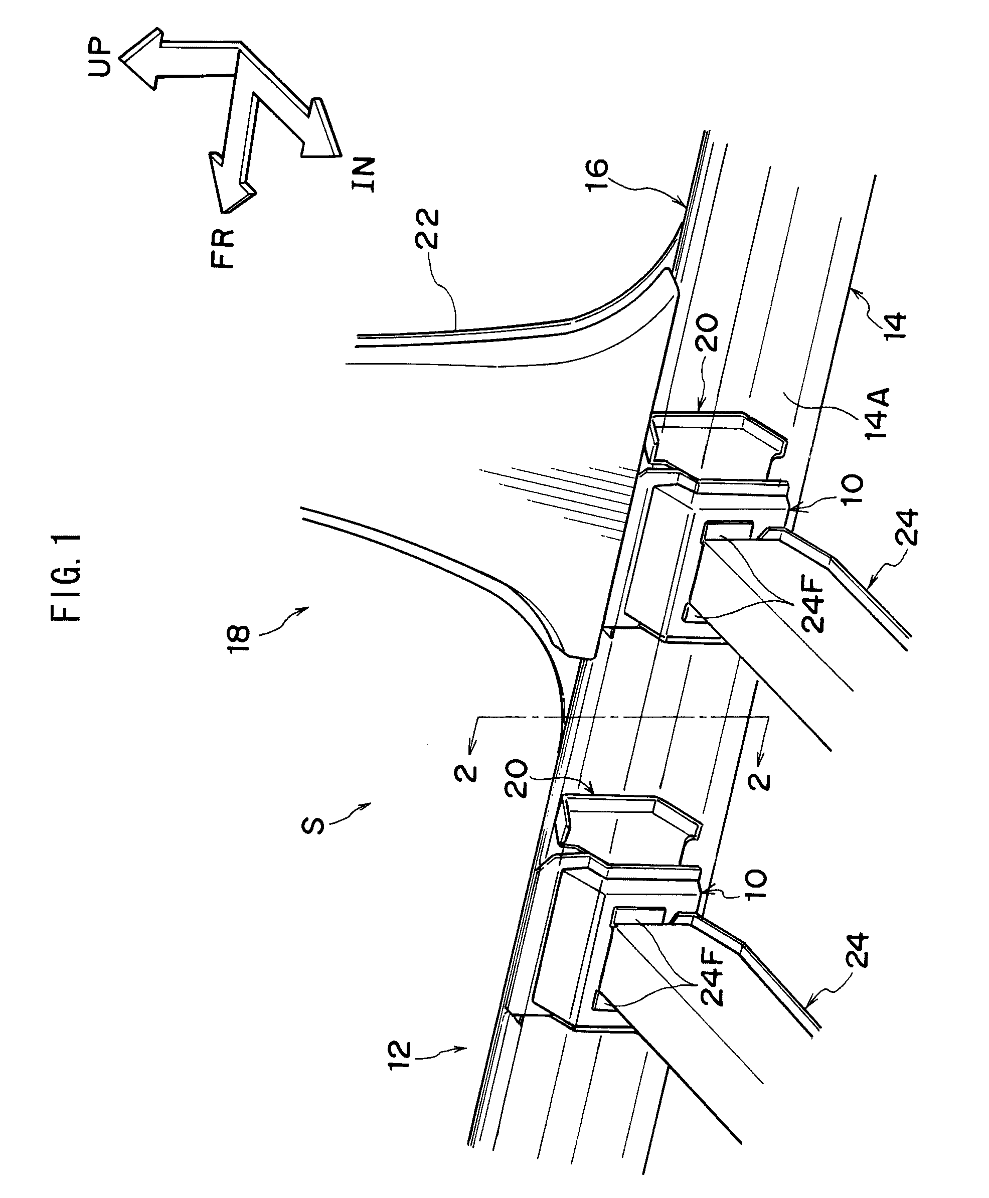
[0025]Next, an exemplary embodiment of the present invention will be explained based on the drawings. In FIG. 1, a vehicle body lower structure S according to the embodiment comprises a locker 12, a first reinforcing member 10, and a second reinforcing member 20.

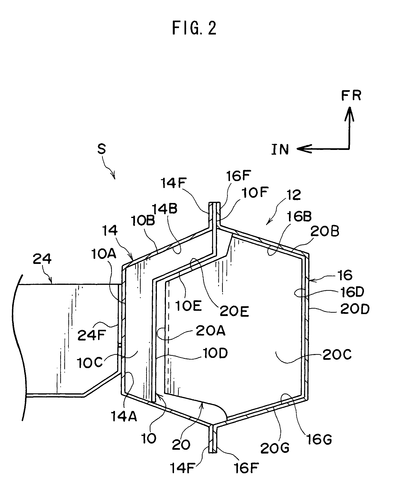
[0026]Locker 12 is formed by joining a locker inner panel 14, and a locker outer panel 16, and a locker extends in a vehicle front-rear direction at each of the left and right sides of a lower portion of vehicle body 18. As shown in FIG. 2, locker inner panel 14 is formed in a substantial “hat” shape in cross section, projecting towards a vehicle lateral direction inner side, while locker outer panel 16 is formed in a substantial “hat” shape in cross section, projecting towards a vehicle lateral direction outer side, and they form a closed cross section, owing to spot welding or the like at upper and lower flanges 14F and 16F. As shown in FIG. 1, a lower portion of B-pillar 22, as an example of a pillar, is joined to a porti...


PUM


Abstract

An object is to suppress vehicle body deformation in a side collision without sacrificing a vehicle interior space.Provided is a first reinforcing member 10 disposed in a locker 12 at a vehicle lateral direction inner side, and a second reinforcing member 20 disposed in locker 12 at a vehicle lateral direction outer side, which opposes first reinforcing member 10 in a vehicle lateral direction, and which is provided with a side surface 20A and an end surface 20E (engaging portions) that engage with first reinforcing member 10 when locker 12 deforms. When locker 12 begins to deform due to a side collision to a vehicle 18, end surface 20E of second reinforcing member 20 contacts and engages flange 10E of first reinforcing member 10, and a torsional deformation can be suppressed, and side surface 20A contacts flange 10D, and a crushing deformation of locker 12 in a vehicle lateral direction can be suppressed. Since first reinforcing member 10 and second reinforcing member 20 are provided in locker 12, vehicle interior space is not sacrificed.

Description

CROSS-REFERENCE TO RELATED APPLICATIONS[0001]This application is a national phase application of International Application No. PCT / JP2007 / 059756, filed May 11, 2007, and claims the priority of Japanese Application No. 2006-148625, filed May 29, 2006, the contents of both of which are incorporated herein by reference.TECHNICAL FIELD[0002]The present invention relates to a vehicle body lower structure.BACKGROUND ART[0003]A vehicle body lower structure has been disclosed in which, in order to suppress rotational displacement of a locker in a side collision, a projecting portion is provided that projects from the locker to a vehicle inner side, and as a result of the projecting portion meeting resistance at a floor panel, rotational deformation of the locker is suppressed (see Japanese Utility Model Application Laid-Open (JP-U) No. 3-71981).[0004]However, in the above conventional example, since the projecting portion projects from the locker to a vehicle inner side, a vehicle interior ...

Claims


Application Information

Patent Timeline
21 Jun 2011
Publication
US7963588B2
IPC
B62D21/15
CPC
B62D21/157; B62D25/04; B62D25/025; B62D25/20; B62D21/02; B62D21/00
Inventors
KANAGAI, SHUNSUKE; SARADA, AKIHIRO