Voltage controlled oscillator

a voltage control and oscillator technology, applied in the field of oscillators, can solve the problems of reducing the oscillation frequency f, requiring a relatively small equivalent resonance capacitor, and reducing the design circuit of the transmitter, so as to achieve the effect of high-frequency increas

Active Publication Date: 2011-10-11
IND TECH RES INST
View PDF5 Cites 10 Cited by
  • Summary
  • Abstract
  • Description
  • Claims
  • Application Information

AI Technical Summary

Benefits of technology

[0011]Base on the above, it is not required to adjust the frequency of the VCO by using the variable capacitor in the embodiment of the invention. Instead, the amount of the current of the resonance transistor is changed to adjust the frequency of the VCO. Accordingly, the limitation of the constant capacitor can be disregarded. The oscillation frequency can be highly increased by using the current tuned technique in the embodiment of the invention. Furthermore, the VCO of the embodiment of the invention does not require limiting to the oscillation frequency and the tuning range.

Problems solved by technology

Accordingly, the design of the circuit of the transmitter is more difficult and has more challenges.
Unfortunately, for some capacitance, if the VCO is desired to operate at high frequency, the equivalent resonance capacitor requires being relatively reduced.
However, it may reduce the oscillation frequency fOSC because the total equivalent capacitance become larger.
In the design of high frequency circuit, it is affected considerably.

Method used


Image

  • Voltage controlled oscillator
  • Voltage controlled oscillator
  • Voltage controlled oscillator

Examples


Embodiment Construction

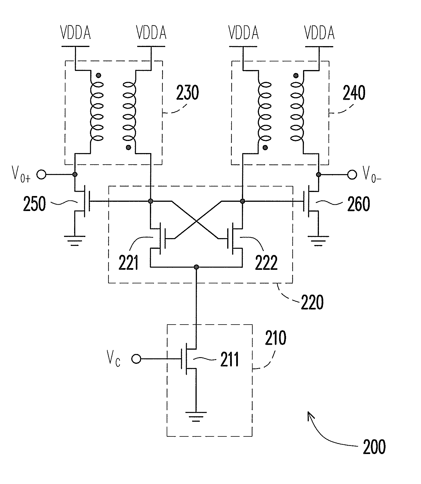
[0024]One embodiment of the invention provides a voltage controlled oscillator (VCO). Without the variable capacitor, the VCO can increases the oscillation frequency outputted thereby, and further the requirement of the higher oscillation frequency is provided.

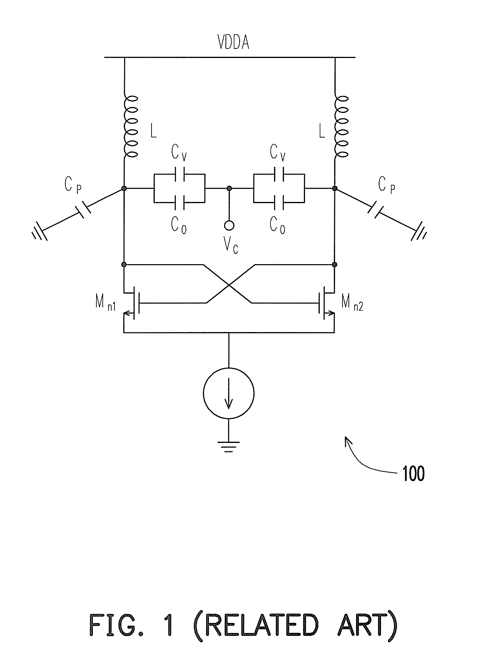
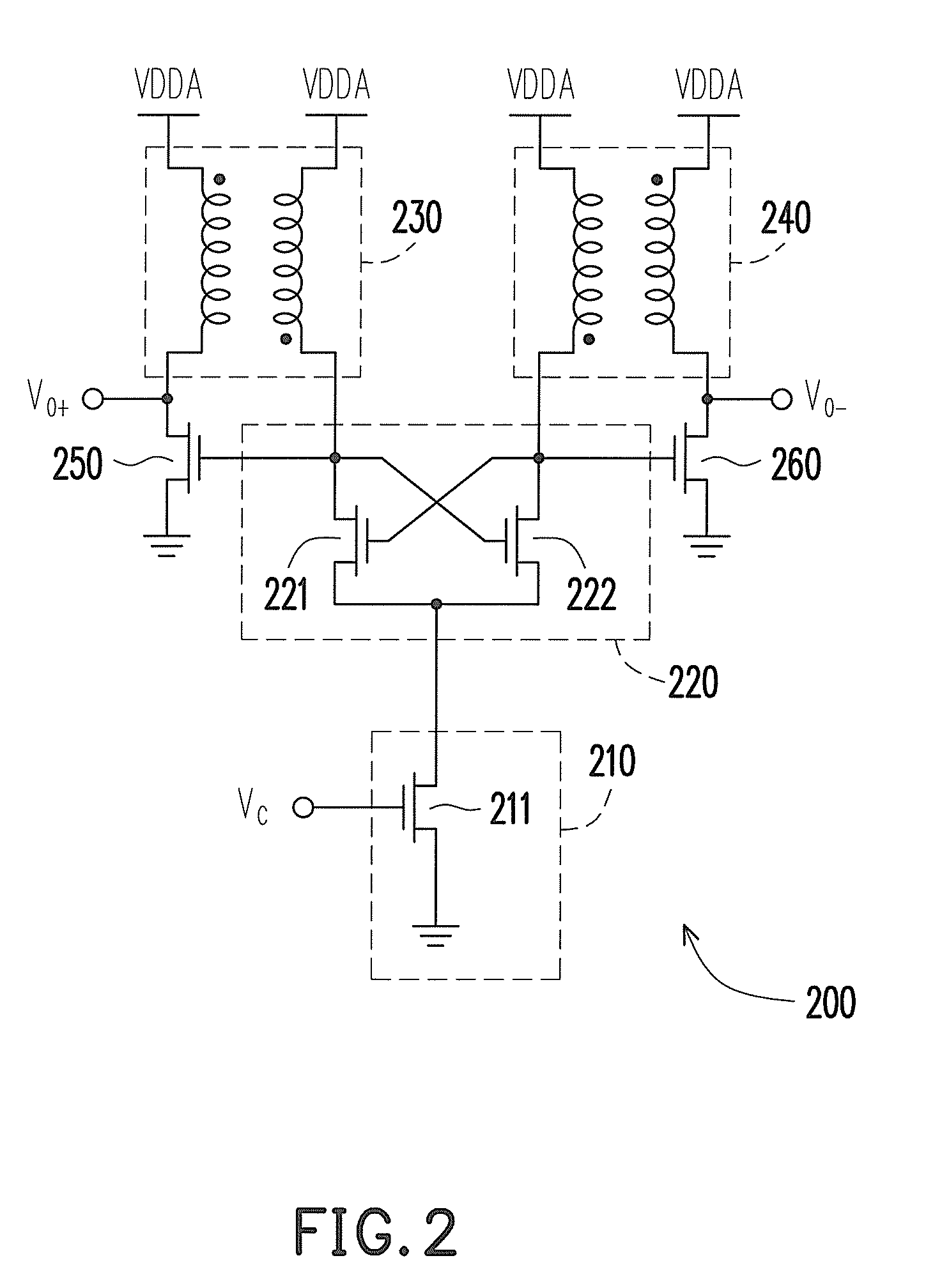
[0025]In order to improve the issue related to trade off between the oscillation frequency and the tuning range in the conventional VCO, the variable capacitor is not used in the following embodiments. Instead, by changing the amount of the current of the resonance transistor, the change of the frequency is achieved. FIG. 2 is a schematic circuit diagram of a VCO according to an embodiment of the invention. Referring to FIG. 2, the VCO 200 includes a voltage controlled current source (VCCS) 210, a negative resistance circuit (NRC) 220, a first transformer 230, a second transformer 240, a first transistor 250, and a second transistor 260. In the present embodiment, the transistors 250 and 260 are both NMOS transistors (N-channe...


PUM


Abstract

A voltage controlled oscillator (VCO) includes a voltage controlled current source (VCCS), a negative resistance circuit (NRC), a first transformer, a second transformer, a first transistor and a second transistor. A current terminal of the VCCS receives a control voltage. First terminals of first and second current paths in the NRC are coupled to a current terminal of the VCCS. Primary sides of the first and the second transformers are respectively coupled to second terminals of the first and the second current paths. Secondary sides of the first and the second transformers are first and second output terminals of the VCO, respectively. First terminals of the first and the second transistor are respectively coupled to the secondary sides of the first and the second transformers. Control terminals of the first and the second transformers are respectively coupled to the primary sides of the first and the second transformers.

Description

CROSS-REFERENCE TO RELATED APPLICATION[0001]This application claims the priority benefit of Taiwan application serial no. 98124898, filed on Jul. 23, 2009. The entirety of the above-mentioned patent application is hereby incorporated by reference herein and made a part of specification.BACKGROUND[0002]1. Technical Field[0003]The present invention generally relates to an oscillator, and more particularly, to a wide bandwidth voltage controlled oscillator using a negative resistance technique.[0004]2. Description of Related Art[0005]In recent years, due to the development of the wireless communication, the manufacturing technology of integrated circuit (IC) has a violent variation within a short time, especially for the circuit of the transmitter applied in radio frequency (RF). With rapid progress in semiconductor manufacturing technology, the current application of IC at Giga Hertz becomes wider and wider, and even progresses to higher operation frequency. Accordingly, the design of...

Claims


Application Information

Patent Timeline
Patent Type & Authority Patents(United States)
IPC IPC(8): H03B5/08
CPCH03B5/1225H03B5/1228H03B5/1296H03B5/1215H03B5/1221H03B5/1253H03B5/1271
Inventor CHANG, CHIH-HSIANGLIN, JUNG-MAOYANG, CHING-YUAN
Owner IND TECH RES INST
Why Eureka
Try Eureka