Connector

a technology of connecting rods and connectors, applied in the direction of coupling contact members, coupling device connections, electric discharge lamps, etc., can solve the problems of small power loss during voltage transformation and power transmission, undesirable effects on human body and electronic parts, etc., and achieve the effect of safe transmission of power

Inactive Publication Date: 2012-02-28
NTT FACILITIES INC
View PDF11 Cites 4 Cited by
  • Summary
  • Abstract
  • Description
  • Claims
  • Application Information

AI Technical Summary

Benefits of technology

[0009]Another and more specific object of one aspect of the present invention is to provide a connector and a combination of male and female connectors, which can safely transmit power in a form of a high voltage.

Problems solved by technology

According to such power transmissions, the power loss during the voltage transformation and power transmission is small, and it is unnecessary to increase the cross sectional size of cables.
But when supplying power to the electronic apparatus, there may be undesirable effects on the human body and on the electronic parts if the power is supplied in the form of a high voltage.

Method used


Image

  • Connector
  • Connector
  • Connector

Examples


first embodiment

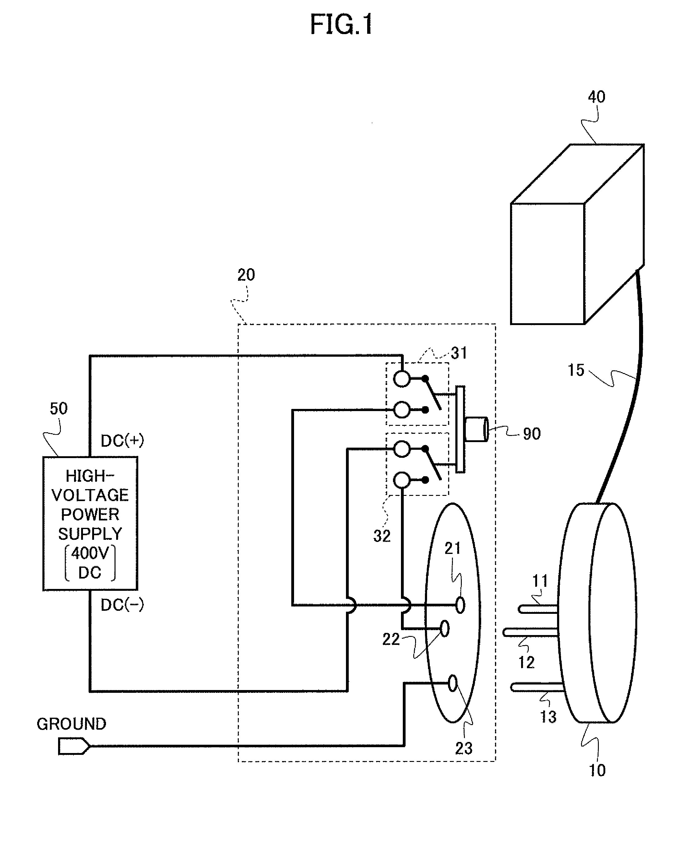
[0023]FIG. 1 is a diagram for explaining electrical connections or electrical couplings of connectors in the present invention.

[0024]In this embodiment, the combination of male and female connectors include a male connector 10 and a female connector 20. The male connector 10 is connected to an information processing apparatus 40, such as a server and a computer, via a power cable 15. The male connector 10 includes two power plug terminals 11 and 12 for receiving power, and a ground plug terminal 13 for grounding.

[0025]On the other hand, the female connector 20 is connected to a high-voltage power supply 50 for supplying power. The female connector 20 includes power jack terminals 21 and 22 which correspond to the power plug terminals 11 and 12, and a ground jack terminal 23 which corresponds to the ground plug terminal 13. The female connector 20 further includes two control switches 31 and 32. For example, the control switches 31 and 32 are respectively formed by a leaf spring swit...

second embodiment

[0056]FIGS. 8A, 8B, 8C and 8D are diagrams showing a structure of a male connector of the present invention. FIG. 8A shows a bottom view of a male connector 110 of this embodiment, FIG. 8B shows a front view of the male connector 110, and FIG. 5C shows a top view of the male connector 110.

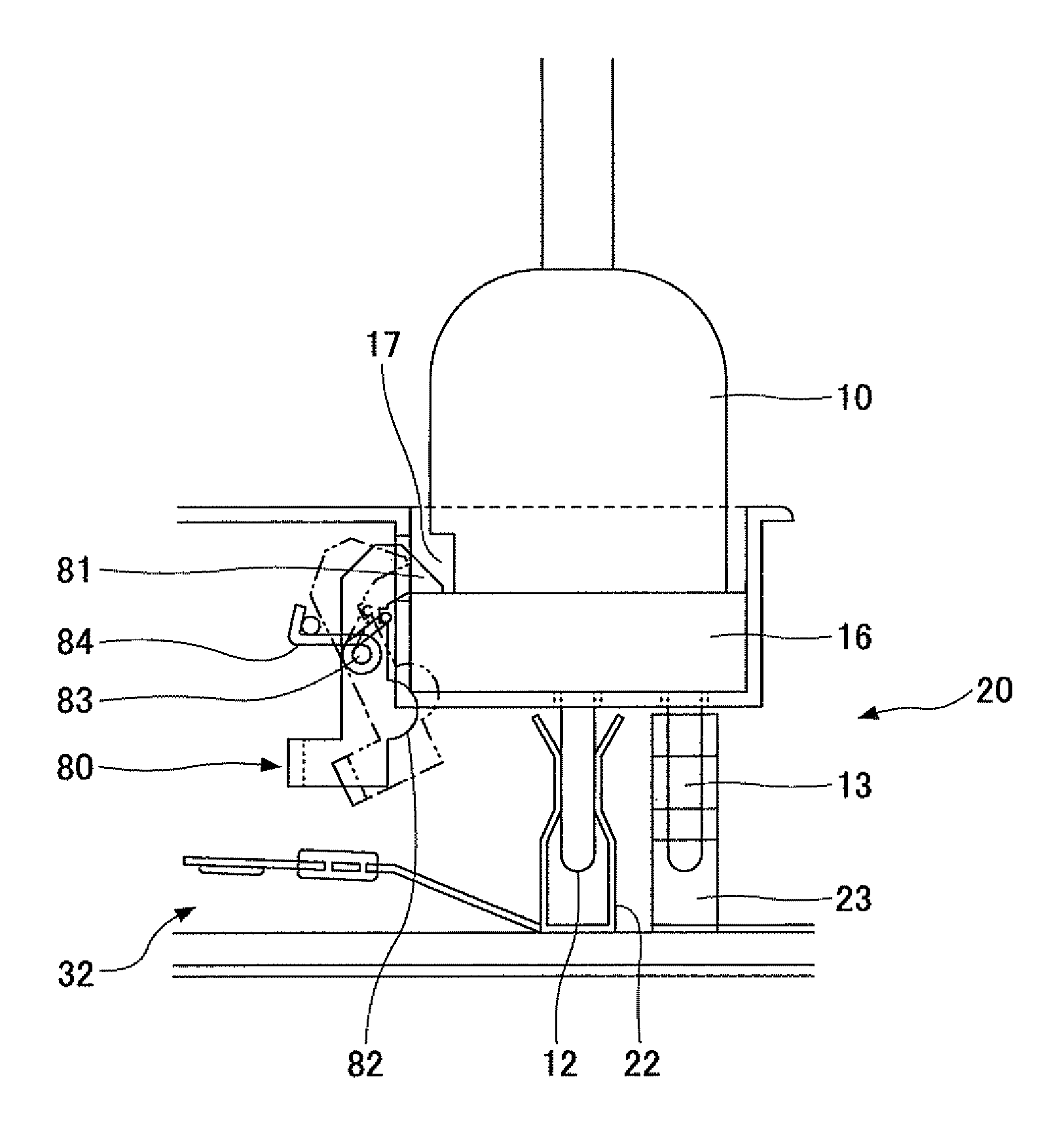
[0057]In this embodiment, the male connector 110 has flange 116. Power plug terminals 111 and 112, a ground plug terminal 113, and a pin 114 are provided on the flange 116. The pin 114 extends parallel to the plug terminals 111 through 113. A main body of the male connector 110 is connected to a power cable 115, and the main body has a locking part 117. A portion of the main body is removed along a direction in which the male connector 110 is inserted with respect to a female connector 120, in order to form the locking part 117. As will be described later, the flange 116 has a function of turning a releasable lock 180 of the female connector 120 in order to lock the male connector 110 and the femal...


PUM


Abstract

A female connector for supplying received power has a recess, terminals including power terminals for supplying the power, a locking mechanism to lock a male connector that is inserted into the recess in a mated state in response to insertion of the male connector into the recess, and a switching mechanism to supply the received power to the power terminals in an ON state and to insulate the power terminals from the received power in an OFF state. The switching mechanism is permitted to make a transition to the ON state only when the locking mechanism is locking the male connector in the mated state.

Description

BACKGROUND OF THE INVENTION[0001]1. Field of the Invention[0002]The present invention generally relates to connectors, and more particularly to a connector that is suited for supplying power, and to a combination of male and female connectors.[0003]2. Description of the Related Art[0004]Generally, an electronic apparatus needs to receive power from a power supply in order to perform an operation. Usually, the power from the power supply is supplied to the electronic apparatus via connectors. The connectors that are used to make the electrical connection include a male connector and a female connector that are designed to mate. Examples of such connectors are proposed in Japanese Laid-Open Patent Publications No. 5-82208 and No. 2003-31310, for example.[0005]On the other hand, as a countermeasure against global warming, power transmissions in local areas using high DC voltages are being studied. According to such power transmissions, the power loss during the voltage transformation a...

Claims


Application Information

Patent Timeline
Patent Type & Authority Patents(United States)
IPC IPC(8): H01R29/00
CPCH01R13/707H01R13/04H01R13/10H01R13/20H01R13/66
Inventor NAKAMURA, AKIOYUBA, TAKASHIHIROSE, KEIICHIIINO, TOMONORI
Owner NTT FACILITIES INC
Why Eureka
Try Eureka