Check patentability & draft patents in minutes with Patsnap Eureka AI!

Liquid crystal display device having common electrode being formed on color filter patterns

a color filter pattern and liquid crystal display technology, applied in the direction of optics, instruments, optical filters, etc., can solve the problems of lowering luminance, difficult to use a relatively simple spinless coating method, and inability to completely shield ligh

Active Publication Date: 2012-05-29
LG DISPLAY CO LTD
View PDF20 Cites 2 Cited by
  • Summary
  • Abstract
  • Description
  • Claims
  • Application Information

AI Technical Summary

Benefits of technology

This approach results in uniform light-shielding patterns, enabling the use of simpler coating methods and improving luminance by preventing step coverage and ensuring complete light shielding.

Problems solved by technology

Thus, when the color filter patterns 16 are formed, it is difficult to use a relatively simple spinless coating method.
Accordingly, it is impossible to completely shield the light, thereby lowering the luminance.

Method used


Image

  • Liquid crystal display device having common electrode being formed on color filter patterns
  • Liquid crystal display device having common electrode being formed on color filter patterns
  • Liquid crystal display device having common electrode being formed on color filter patterns

Examples


Embodiment Construction

[0039]Reference will now be made in detail to the preferred embodiments of the present invention, examples of which are illustrated in the accompanying drawings. Wherever possible, the same reference numbers will be used throughout the drawings to refer to the same or like parts.

[0040]Hereinafter, an LCD device and a method for fabricating the same according to an embodiment of the present invention will be described with reference to the accompanying drawings.

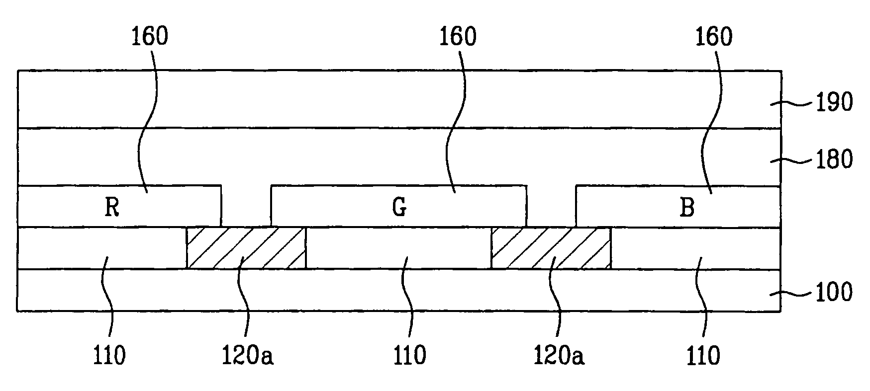
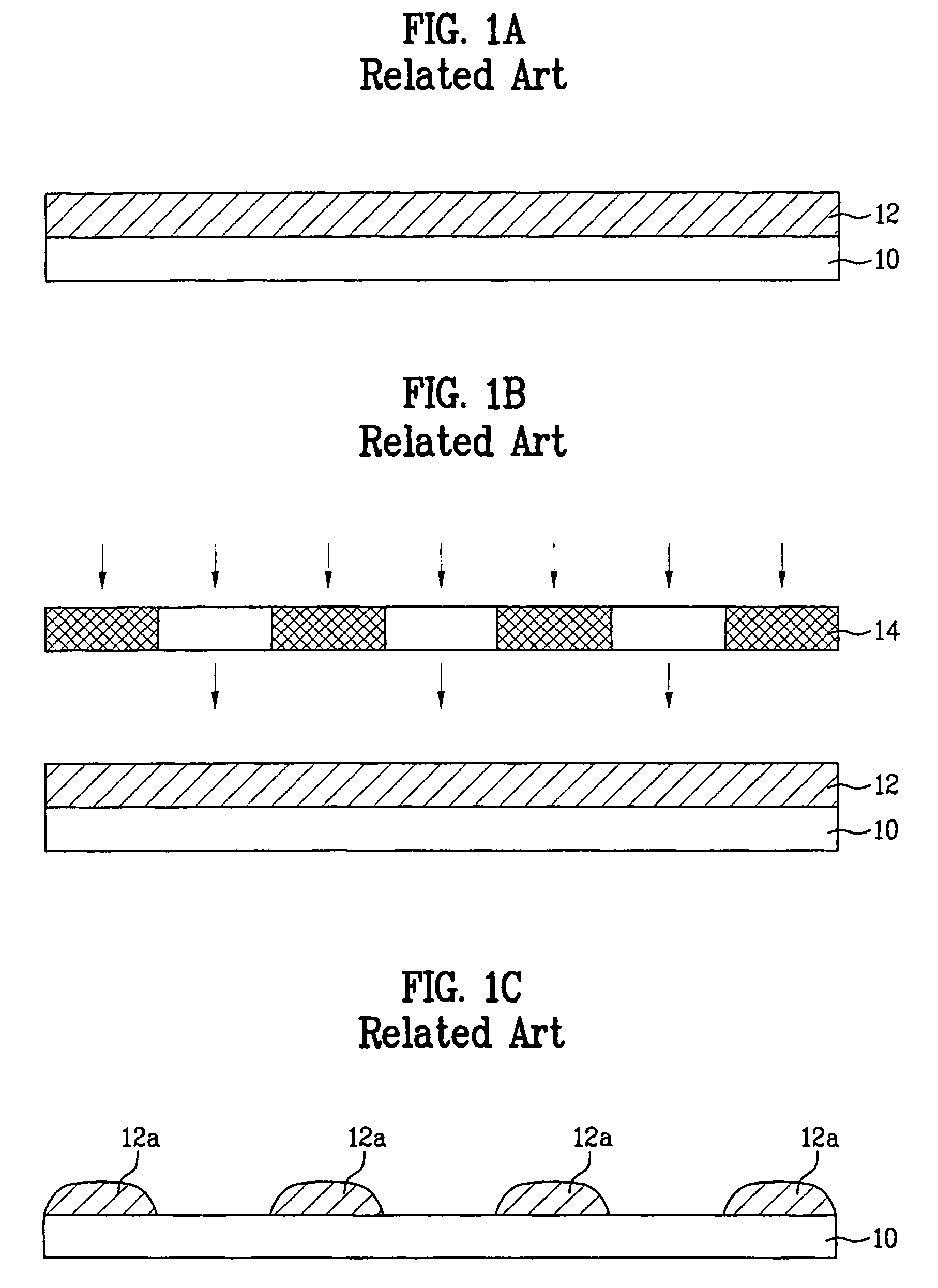
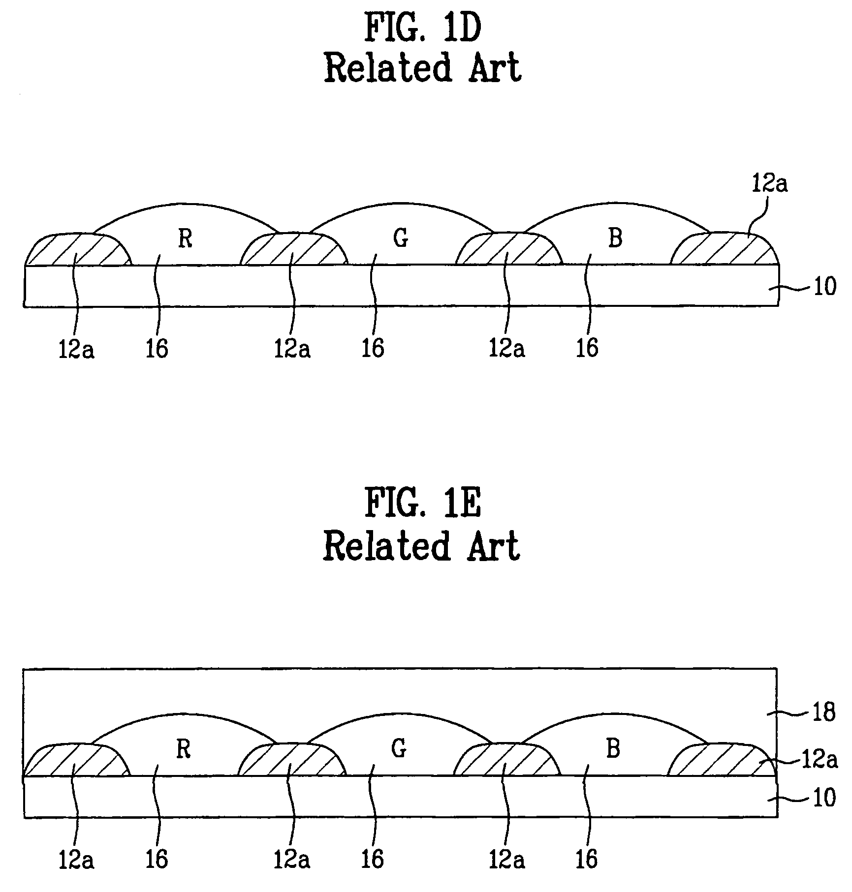
[0041]FIGS. 2A to 2G are cross sectional views of the process for fabricating a color filter substrate according to an embodiment of the present invention.

[0042]As shown in FIG. 2A, a transparent material layer 110 is coated on a substrate 100. The transparent material layer 110 may be formed from a transparent photosensitive resin. It is preferable to use an acrylic type resin as the transparent photosensitive resin, for example, acrylate, methacrylate, acrylamide, acrylonytrile, acrylic acid or methacryl.

[0043]Referring to F...


PUM

PropertyMeasurementUnit
transparentaaaaaaaaaa
thicknessaaaaaaaaaa
heightsaaaaaaaaaa

Abstract

An LCD device and a method for fabricating the same is described, in which each of light-shielding patterns has the uniform thickness to prevent the step coverage from being generated in color filter patterns by the light-shielding patterns. The LCD device includes a substrate with pixel and light shielding regions definede, a transparent material layer formed on the substrate corresponding to the pixel regions, a light-shielding layer formed on the substrate corresponding to the light shielding regions, and a color filter layer on the transparent material layer.

Description

[0001]This application claims the benefit of Korean Patent Application No. 10-2004-0089308 filed in Korea on Nov. 4, 2004, which is hereby incorporated by reference as if fully set forth herein.BACKGROUND OF THE INVENTION[0002]1. Field of the Invention[0003]The present invention relates to a liquid crystal display (LCD) device, and more particularly, to a color filter substrate of an LCD device.[0004]2. Discussion of the Related Art[0005]Among various ultra-thin flat type display devices, which include a display screen having the thickness of several centimeters (cm), a liquid crystal display (LCD) device attracts great attentions in that it has advantages such as low power consumption due to low driving voltage and portability. In this respect, the LCD device can be widely used for notebook computers, monitors, aircraft, and etc.[0006]Generally, the LCD device includes a thin film transistor (TFT) substrate, a color filter substrate, and a liquid crystal layer. The TFT substrate is...

Claims


Application Information

Patent Timeline
Patent Type & Authority Patents(United States)
IPC IPC(8): G02F1/1335G02F1/1333G02B5/20
CPCG02B5/201G02F1/133512G02F1/133516G02B5/20G02F1/133509G02F1/136209G02F1/1335
Inventor KIM, CHUL HOLEE, JUNG JAE
Owner LG DISPLAY CO LTD
Features
  • R&D
  • Intellectual Property
  • Life Sciences
  • Materials
  • Tech Scout
  • Unparalleled Data Quality
  • Higher Quality Content
  • 60% Fewer Hallucinations
Learn More