Self-powered in-pipe fluid meter and piping network comprising a plurality of such fluid meters

a fluid meter and self-powered technology, applied in the field of fluid meter, can solve the problems of battery replacement or replacement, presently used sensors, and water quality degradation only apparent, and achieve the effects of reducing maintenance costs, improving safety and life, and being convenient and cheap to opera

Inactive Publication Date: 2012-10-30
AGENCY FOR SCI TECH & RES
View PDF8 Cites 6 Cited by
  • Summary
  • Abstract
  • Description
  • Claims
  • Application Information

AI Technical Summary

Benefits of technology

[0009]An aspect of the present invention is the employment of a fluid-driven power source unit such as a hydraulically driven power source unit, which is capable of supplying a continuous supply of electricity to the fluid meter and its associated electrical modules / units. Another aspect is the employment of telemetry, for example, acoustic-wave telemetry, which allows for data transmission to and from the remote fluid sensor / meter without an on-surface module, that is, from inside of the pipe. Both aspects allow the remote flow sensor of the present invention to be a totally in-pipe solution and thereby increase system security and extend the lifespan of the fluid sensor.
[0017]The fluid meter according to the present invention allows for a total in-pipe implementation of the entire fluid meter, that is, the fluid meter can be entirely mounted within the pipe without having any on-surface parts (parts being located outside of the pipe such as an antenna or a solar cell unit). For example, the fluid meter can be fixed to the inner surface of the tube by gluing, screwing or via a plug-in connection. Thus, the fluid meter does not need to be protected against damages, for example caused by extreme environmental conditions, and does not need to be regularly surveilled, thereby improving security and lifetime as well as reducing maintenance cost for the fluid meter. Further, the fluid meter according to the present invention can be implemented as a totally self-powered fluid meter not being dependent from any external power source. In other words, the fluid meter can be operated without the aid of an external power source so that it can also be used at isolated places. Further, since the fluid meter uses the fluid flow of the fluid in the pipe, that is, the energy of the fluid, the fluid meter does not have to be accessed or removed from the pipe once it has been installed therein. Thus, the fluid meter according to the present invention is also reliable as well as easy and cheap to operate.

Problems solved by technology

Accordingly, there may be some instances where the degradation in the water quality is only apparent after the change in water quality has caused human illness and / or environmental changes.
However, there exist several problems with the presently used sensors.
The drawbacks of these power sources are that the batteries need to be recharged or replaced due to their very limited lifespan and solar cells can only work properly under restricted environmental and weather conditions.
The drawback here is that such an on-surface module needs to be protected and regularly surveilled, which then introduces significant manpower costs for the monitoring of water distribution networks having large numbers of remote sensors.

Method used


Image

  • Self-powered in-pipe fluid meter and piping network comprising a plurality of such fluid meters
  • Self-powered in-pipe fluid meter and piping network comprising a plurality of such fluid meters
  • Self-powered in-pipe fluid meter and piping network comprising a plurality of such fluid meters

Examples


Embodiment Construction

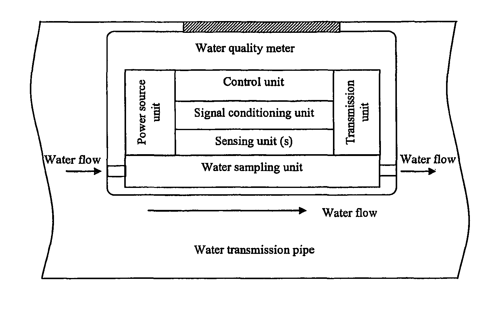
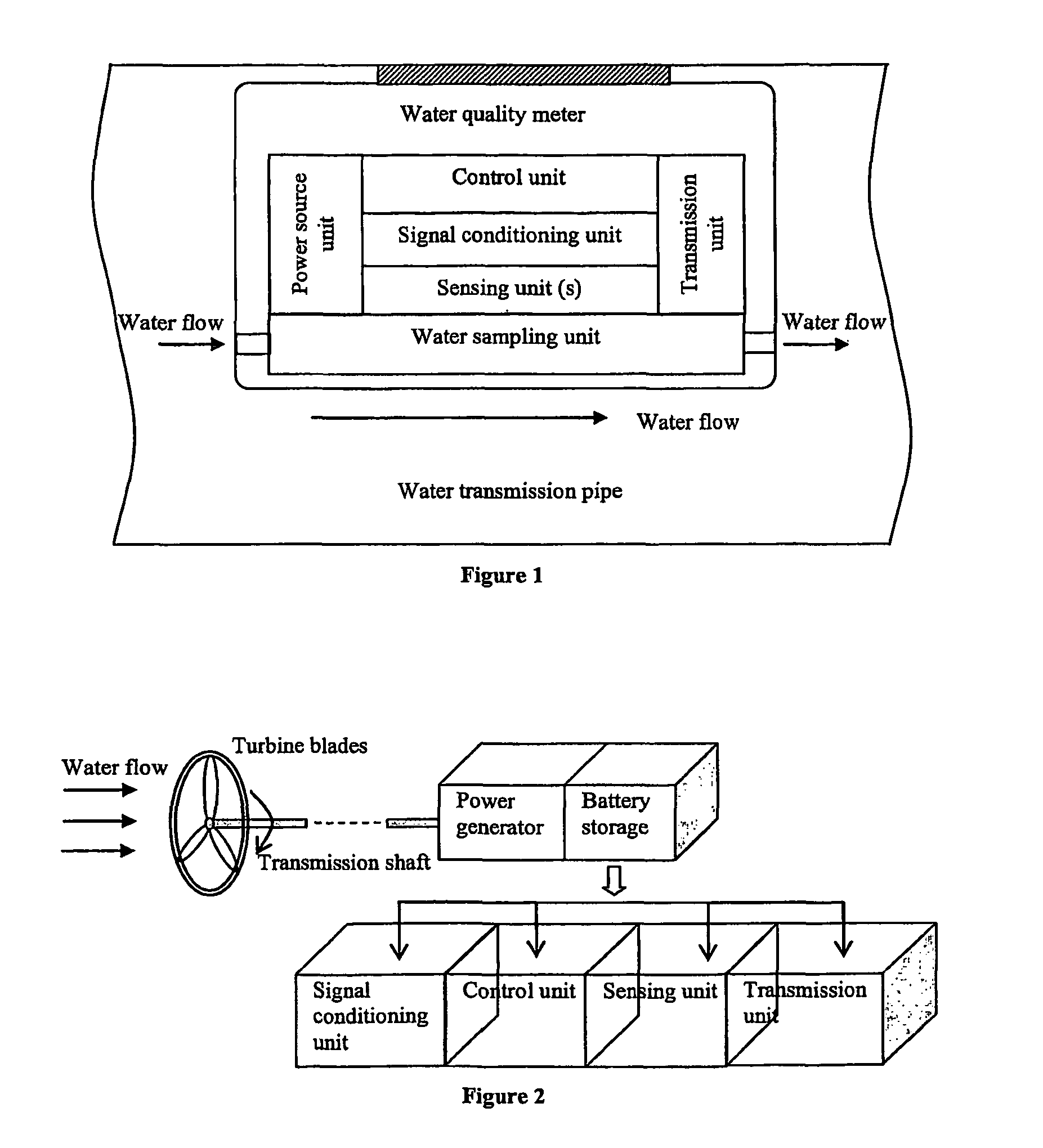
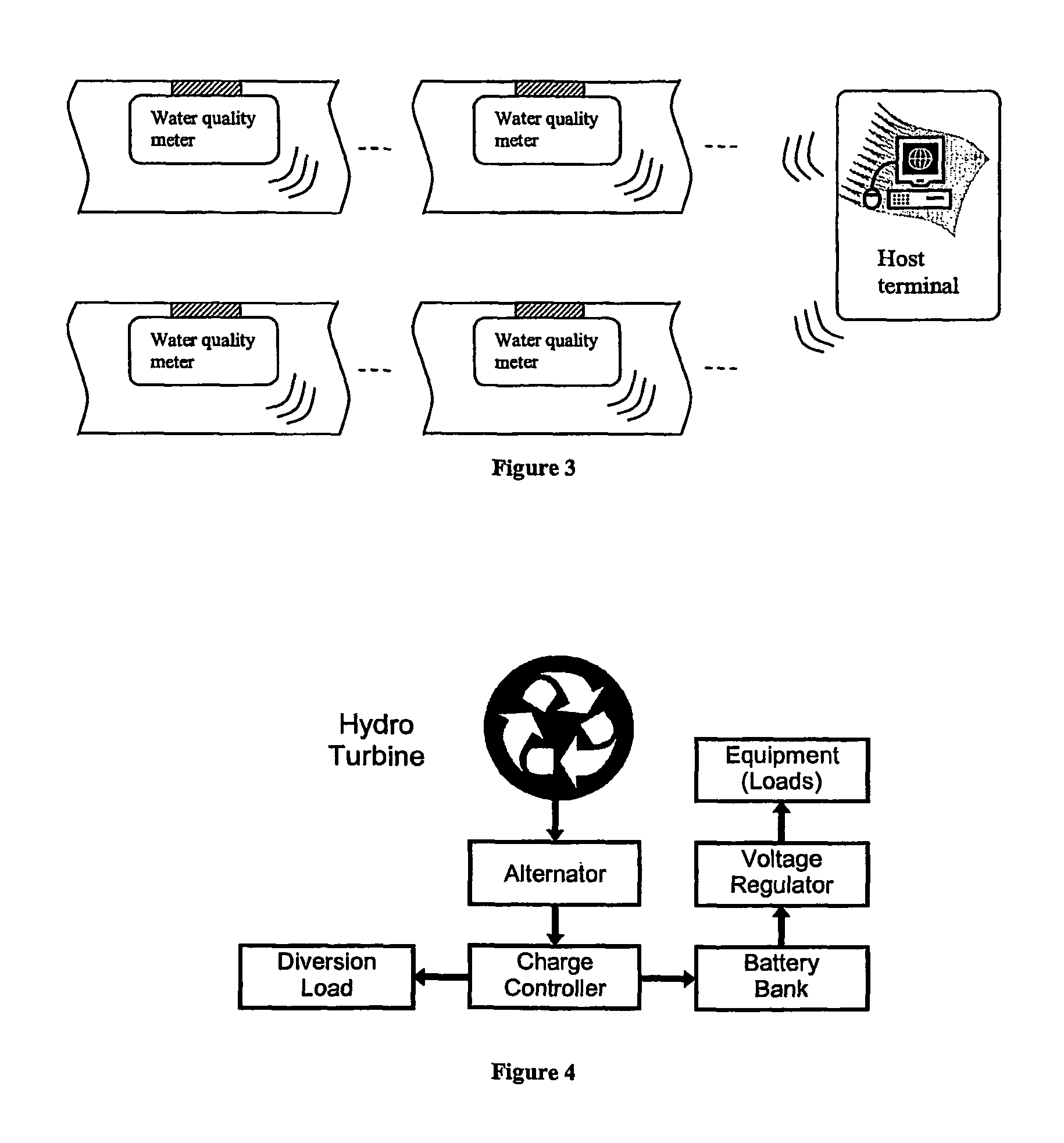
[0026]FIG. 1 shows a schematic block diagram of a water quality meter according to an embodiment of the present invention. The water quality meter is mounted on the inner side of a water transmission pipe. As can be seen in FIG. 3, a plurality of water quality meters of the present invention can be provided in a water transmission piping system, communicating with one or more host terminals. The water quality meter according to this embodiment comprises a water sampling unit, a sensing unit, a signal conditioning unit, a control unit, a power source unit and a transmission unit. The sampling unit extracts / takes a sample from water flowing inside the water transmission pipe and forwards / exposes the sample to the sensing unit. The sensing unit measures several parameters such as the pH-value and forwards the measured parameters to the signal conditioning unit which processes the measured parameters. The processed parameters are then stored in the control unit and send to a host termin...


PUM


Abstract

A self-powered in-pipe fluid meter to be mounted inside of a pipe carrying a fluid therein. The fluid meter comprises at least one sensing unit capable of measuring one or more parameters of the fluid inside of the pipe; a telemetric data transmission unit capable of telemetrically transmitting data including a measured fluid parameter to a host terminal and / or another fluid meter; and at least one fluid-driven power source unit capable of generating power from the fluid flow within the pipe and supplying power to the sensing unit and / or the transmission unit.

Description

CROSS-REFERENCE TO RELATED APPLICATIONS[0001]The present invention claims the benefit of priority of U.S. provisional application No. 60 / 836,257 filed Aug. 7, 2006, the contents of which is hereby incorporated by reference in its entirety for all purposes.FIELD OF THE INVENTION[0002]The present invention relates to fluid meters such as a water quality meter used for monitoring the quality of water in water pipes of a water transmission piping network.BACKGROUND OF THE INVENTION[0003]Historically, the monitoring of water quality in water transmission and distribution systems has been done through the discrete sampling of particular sites of interest and at random intervals. The samples collected are usually processed off-line through wet-chemistry methods. The processing often takes place several days or weeks after the sample has been gathered. Accordingly, there may be some instances where the degradation in the water quality is only apparent after the change in water quality has c...

Claims


Application Information

Patent Timeline
Patent Type & Authority Patents(United States)
IPC IPC(8): G08B23/00
CPCG01F1/10G01F15/063G01N33/18
Inventor WANG, ZHENFENGLIM, SER YOUNFAN, WEIZHANG, DANHONG
Owner AGENCY FOR SCI TECH & RES
Why Eureka
Try Eureka