

Analyzer, ionization apparatus and analyzing method
a mass analyzer and ionization apparatus technology, applied in the field of mass analyzers, can solve the problems of loss of sample ions, difficult simultaneous measurement of a plurality of components as in the measurement of mixture samples, and complex spectrum, so as to reduce loss and increase sensitivity
- Summary
- Abstract
- Description
- Claims
- Application Information
AI Technical Summary
Benefits of technology
Problems solved by technology
Method used
Image

Examples
first embodiment
Shape of Ionization Chamber, and Sample Heating
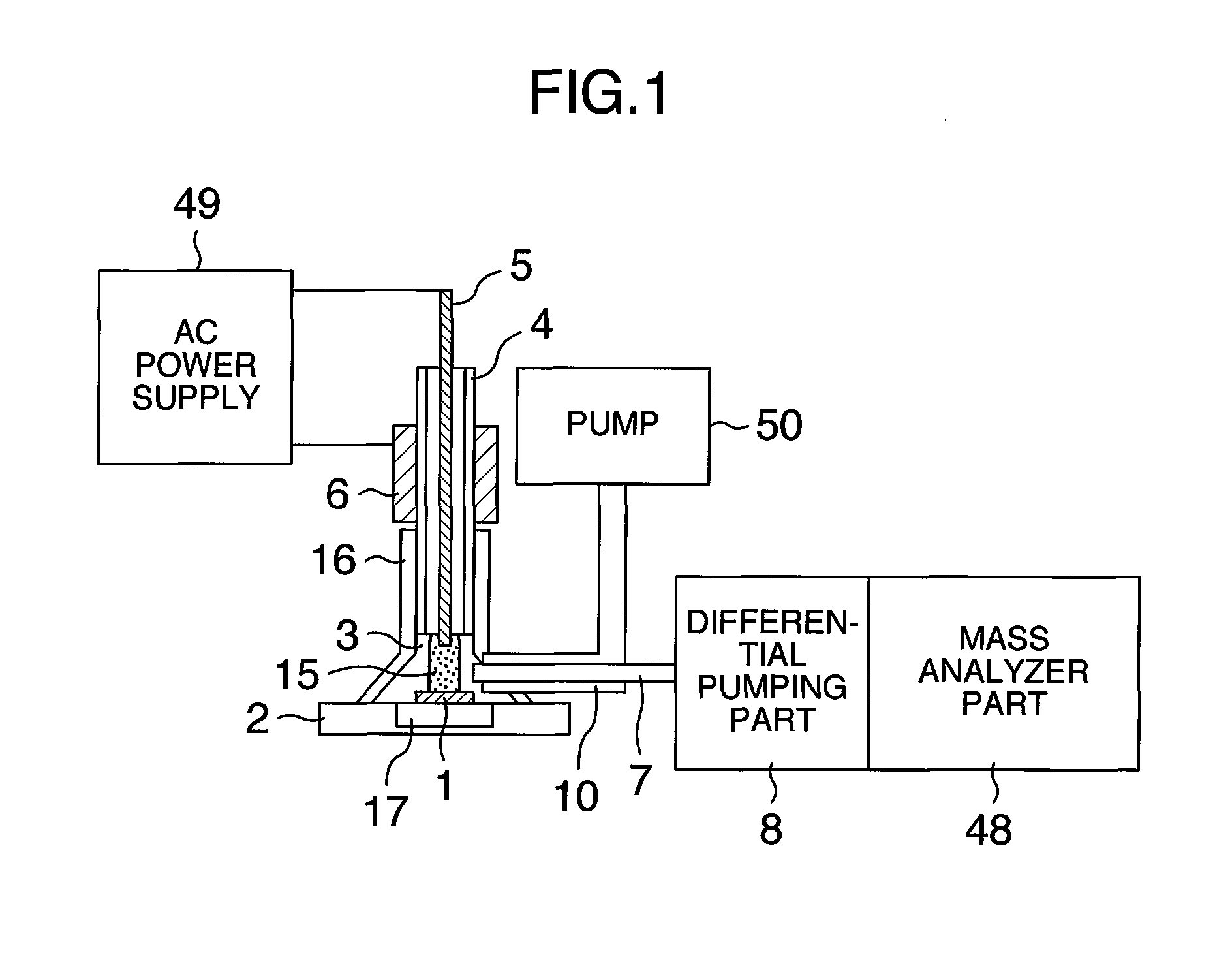
[0033]FIG. 1 illustrates one configuration example of a mass analyzer according to a first embodiment of the present invention.
[0034]An ionization chamber wall 16 has a conical shape. FIG. 1 is a cross sectional view illustrating an ionization chamber. The above-described ionization chamber can reduce a volume of the ionization chamber and shorten the time for evacuation by using a pump, as compared with that having a rectangular parallelepiped. Further, the ionization chamber can keep sample ions in a high concentration while suppressing diffusion of them and improve sensitivity.
[0035]In a sample stage 2, a heater 17 is included and can heat a sample 1. When a vapor pressure of the sample 1 within the ionization chamber 3 is increased, the sensitivity is improved. Since the pressure is reduced by using the pump 50, the sample 1 is evaporated at a temperature lower than that in atmospheric pressure. Therefore, the sample 1 can be evapor...
second embodiment
System Configuration Example
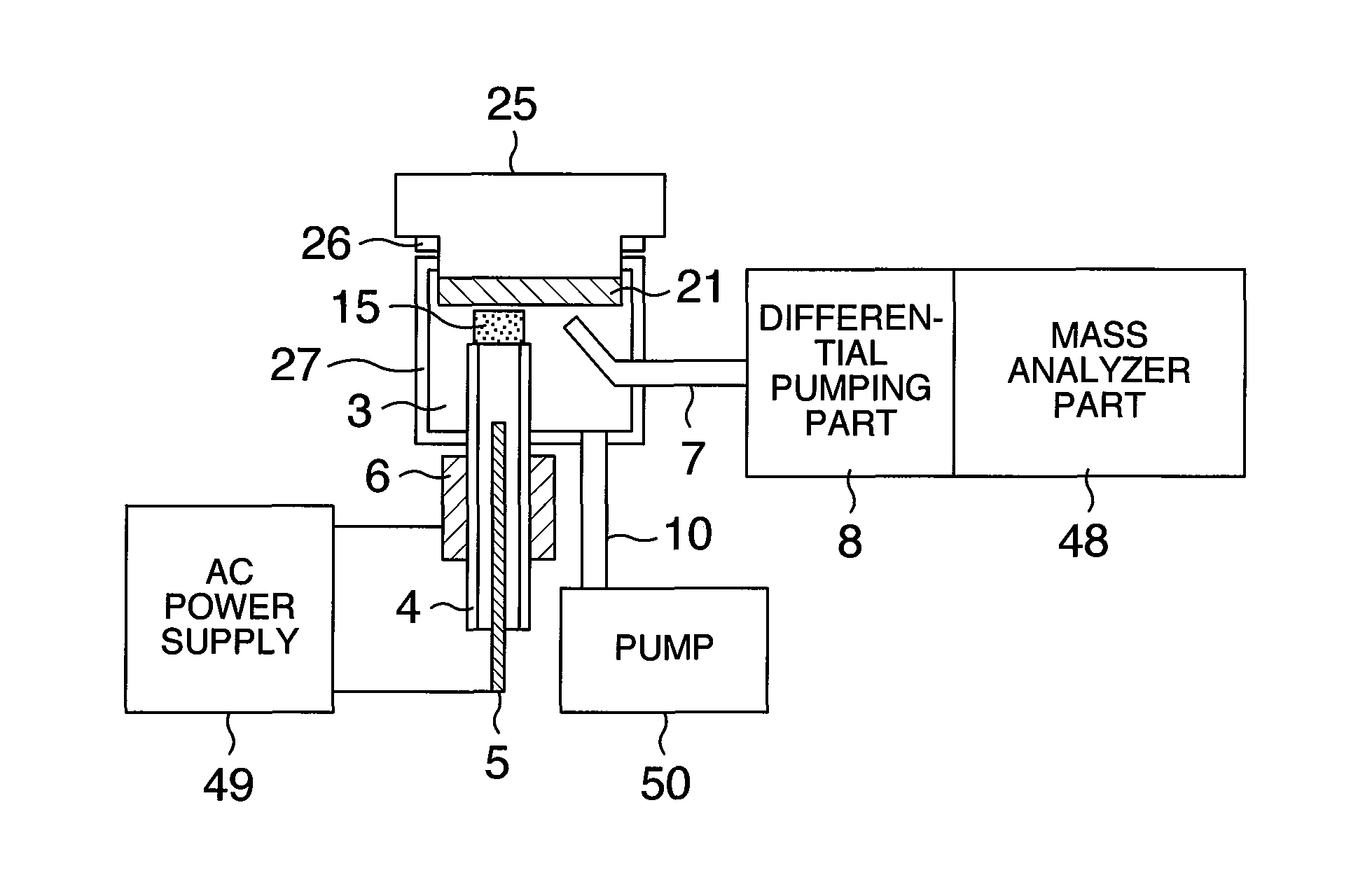
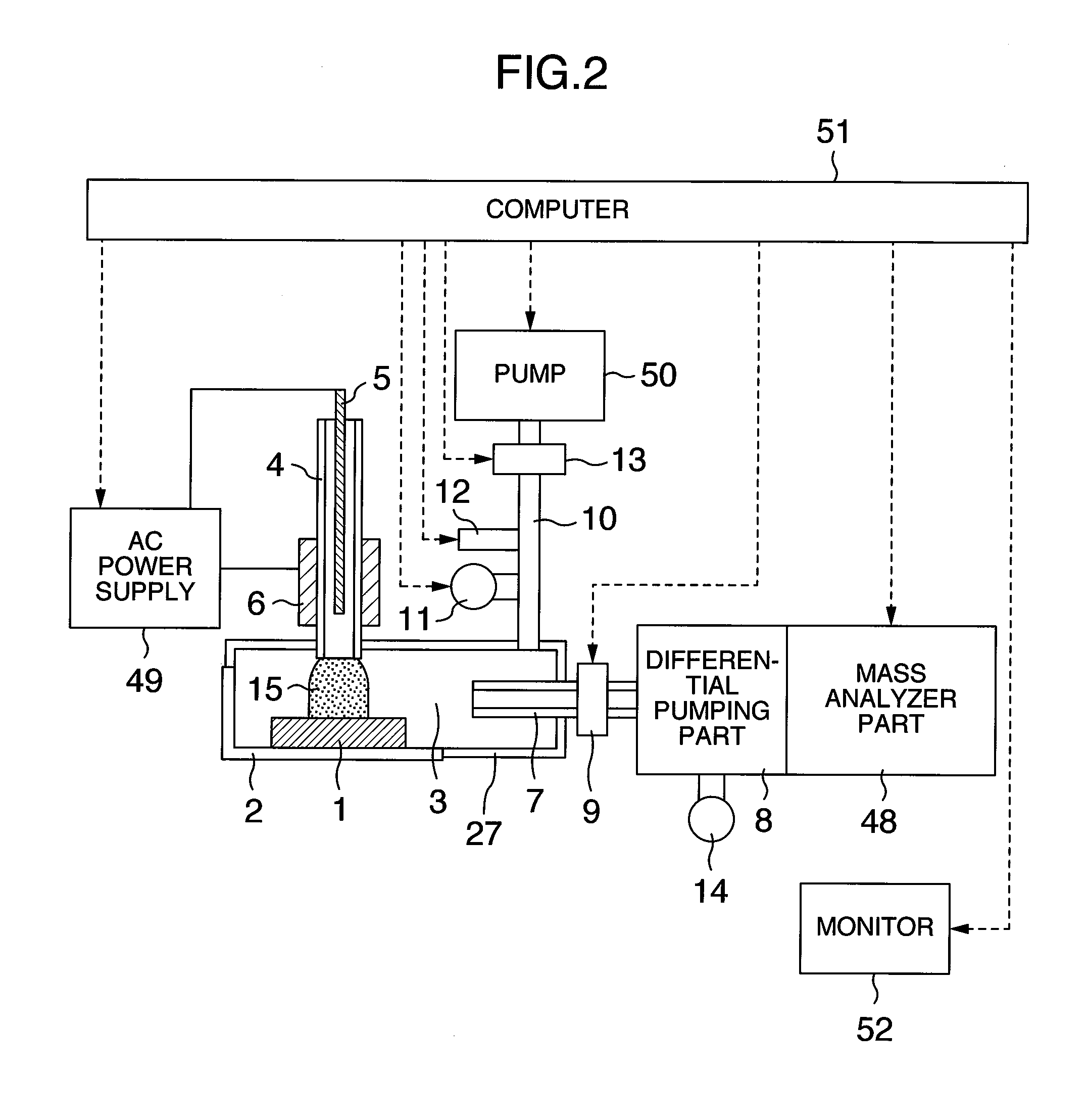
[0041]FIG. 2 illustrates one example of a system configuration of a mass analyzer according to a second embodiment of the present invention.
[0042]The sample 1 is mounted on the sample stage 2, and introduced to the ionization chamber 3. The sample stage 2 that mounts the sample 1 is, for example, cassette-shaped, and one capable of being inserted into the ionization chamber 3 can be used as the sample stage 2. Any of solid, liquid, a substance adsorbed to solid, and a mixture thereof can be used as the sample 1. In the case of using powders or liquid, it may be put into a dish-like vessel. To the ionization chamber 3, a dielectric barrier discharge device is connected. The dielectric barrier discharge device includes the tube 4 that is made of a dielectric such as glass or polymers and that introduces a dielectric barrier discharge gas into the ionization chamber 3, the wire electrode 5 introduced into the tube 4, the electrode 6 installed outside the tub...
third embodiment
Direction of Discharge Tube
[0047]FIG. 3 illustrates one configuration example of a mass analyzer according to a third embodiment of the present invention.
[0048]The sample 1 is mounted on the sample stage 2. A height of the sample stage 2 can be adjusted, and a positional relationship between the sample 1 and each of the introduction tube 4, the ion take-out tube 7, and the exhaust tube 10 can be adjusted. The introduction tube 4 and both of the ion take-out tube 7 and the exhaust tube 10 are disposed so as to sandwich the sample 1 therebetween. The introduction tube 4 may be disposed in parallel with or at a predetermined angle with respect to a top surface of the sample stage 2. The above-described configuration permits the analyzer to efficiently cover a sample surface with the excited molecules and ions generated by the dielectric barrier discharge, improve the ionization efficiency, and further improve the sensitivity.
PUM
 Abstract
Description
Claims
Application Information