Image forming apparatus

a technology of forming apparatus and forming head, which is applied in the direction of electrographic process apparatus, corona discharge, instruments, etc., can solve the problems of noise generation, malfunction of the forming head around the roller shaft, and inability to arrange other parts

Active Publication Date: 2013-03-19
BROTHER KOGYO KK
View PDF19 Cites 5 Cited by
  • Summary
  • Abstract
  • Description
  • Claims
  • Application Information

AI Technical Summary

Benefits of technology

[0008]An object of the present invention is to provide an image forming apparatus which is capable of solving the problem that the roller shaft is electrically floated, and in which a part or parts around the roller shaft can be appropriately arranged.
[0011]According to the present invention, since the roller shaft is grounded via the metal plate, it is possible to solve the problem such as the malfunction of the exposure member, etc., due to electrically floated roller shaft. In addition, since the member supporting the roller shaft and the member for grounding the roller shaft is constructed of the same metal plate, there is no need to provide any additional part for grounding, thereby making it possible to suitably arrange the part or parts around the roller shaft.
[0012]According to the present invention, the metal plate supporting the roller shaft is electrically grounded. This solves the problem due to the otherwise electrically floated roller shaft, as well as makes it possible to suitably arrange the part(s) around the roller shaft.

Problems solved by technology

In this case, there is a fear that the roller shaft might function as a kind of antenna and radiate the electromagnetic wave which the roller shaft received from the outside.
Further, when the electromagnetic wave is radiated from the roller shaft in such a manner, there is a fear that the LED head disposed around the roller shaft might malfunction and / or any noise might be generated.
Furthermore, since the roller shaft is arranged very closely to the LED head and the photoconductive drum, there is a problem such that when a grounding part is attached to the roller shaft, any other part cannot be arranged.

Method used


Image

  • Image forming apparatus
  • Image forming apparatus
  • Image forming apparatus

Examples


Embodiment Construction

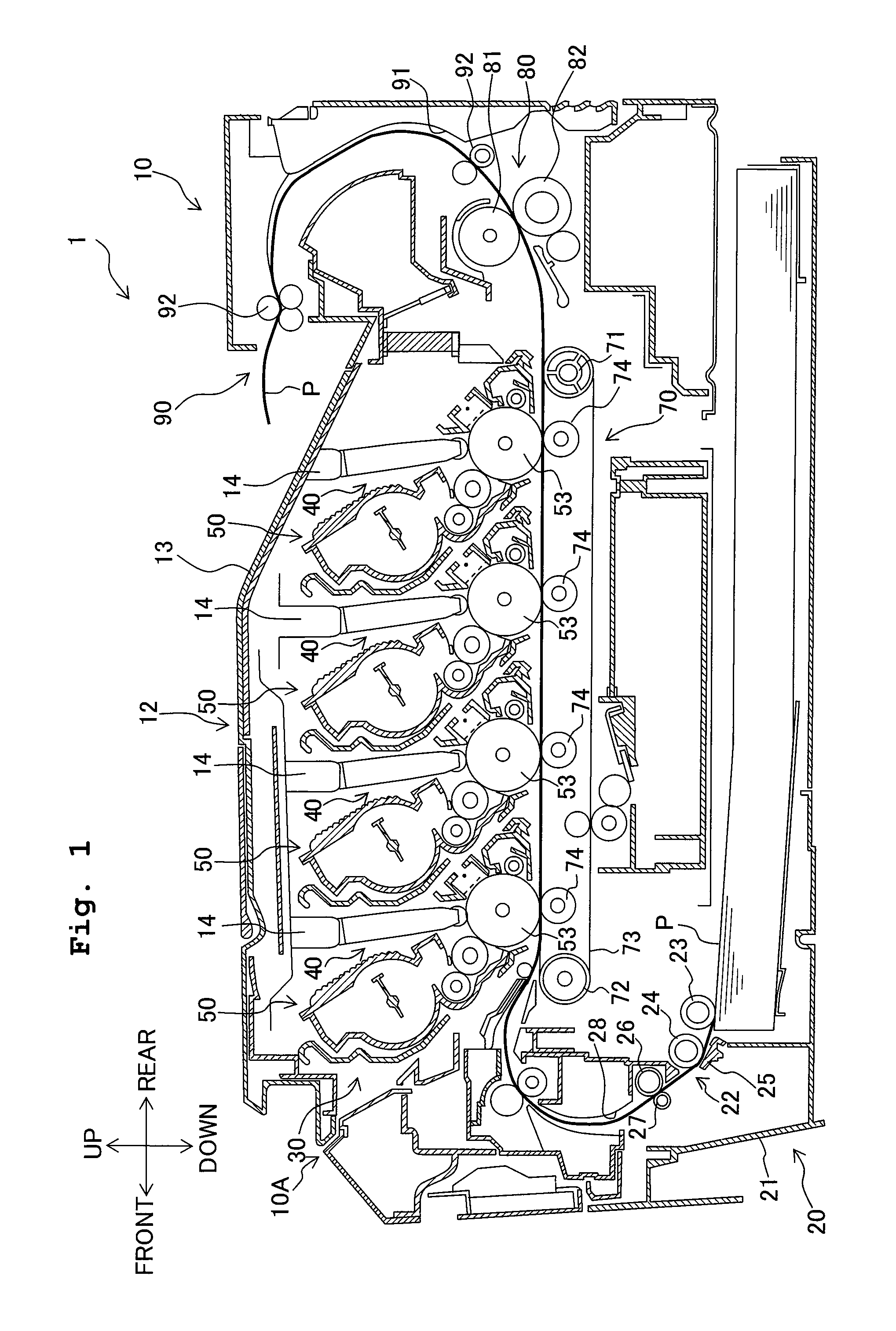
[0021]In the following, a detailed explanation will be given about an embodiment of the present invention, while appropriately referring to the drawings. In the relevant drawings, FIG. 1 is a cross-sectional view of the overall construction of a color printer as an example of image forming apparatus. Note that in the following explanation, the overall construction of the color printer is first described, and then the parts or components characteristic to the present invention will be described.

[0022]The following explanation will be given with the directions, with a user when using the color printer as the reference. Namely, in FIG. 1, the left side on the sheet surface is “front (forward) side”; the right side on the sheet surface is “rear (backward or far) side”; and the up and down direction in the sheet surface is “up and down direction”. Further, in a direction perpendicular to the sheet surface, the far side on the sheet surface is “left side” and the front side on the sheet s...


PUM


Abstract

An image forming apparatus includes a photoconductive body on which an electrostatic latent image is formed; an exposure member which has a plurality of blinking sections and which exposes the photoconductive body; a support frame which is made of resin and which supports the exposure member; a roller shaft which is made of metal and provided on the support frame; a roller which is made of resin, which is rotatably provided on the roller shaft and which maintains a spacing distance between the exposure member and the photoconductive body; and a metal plate which supports and is electrically connected to the roller shaft and which is electrically grounded. With the image forming apparatus, it is possible to solve a problem caused when the roller shaft is electrically floated, and to suitably arrange parts or components around the roller shaft.

Description

CROSS REFERENCE TO RELATED APPLICATION[0001]The present application claims priority from Japanese Patent Application No. 2008-216610 filed on Aug. 26, 2008 the disclosure of which is incorporated herein by reference in its entirety.BACKGROUND OF THE INVENTION[0002]1. Field of the Invention[0003]The present invention relates to an image forming apparatus provided with an exposure member, such as an LED head, which has a plurality of blinking sections (intermittent light-emitting sections).[0004]2. Description of the Related Art[0005]As a conventional image forming apparatus, which exposes a photoconductive (photosensitive) drum with a LED head, there is known an image forming apparatus provided with a support frame which supports the LED head and a roller arranged between the support frame and the photoconductive drum. In this technique, a roller rotatably provided on the support frame is brought into contact with the photoconductive drum to thereby maintain a spacing distance, betwe...

Claims


Application Information

Patent Timeline
Patent Type & Authority Patents(United States)
IPC IPC(8): B41J2/385G03G13/04B41J2/435G03G15/02B41J27/00B41J15/14B41J2/45
CPCG03G15/326G03G15/04054G03G21/1821G03G2215/0409
Inventor SAKAI, TOSHIOTAMARU, YASUOYOKOI, JUNICHISUGIYAMA, YOSUKE
Owner BROTHER KOGYO KK
Why Eureka
Try Eureka