

Base station, terminal, and communication method
a technology of base station and terminal, applied in the direction of signal allocation, digital transmission, transmission path sub-channel allocation, etc., can solve the problem of not conducting sufficient study on a method for arranging cces (control channel elements)
- Summary
- Abstract
- Description
- Claims
- Application Information
AI Technical Summary
Benefits of technology
Problems solved by technology
Method used
Image

Examples
first embodiment
[0061][Overview of Communication System]
[0062]A communication system according to each embodiment of the present disclosure includes a base station 100 and a terminal 200 (UE).
[0063]FIG. 5 is a block diagram illustrating the configuration of a portion of the base station 100 according to an embodiment of the present disclosure. In the base station 100 illustrated in FIG. 5, a signal allocating unit 105 allocates downlink control signals (DCI) to a control channel region (CORESET) constituted by a plurality of control channel elements (CCEs). A transmitting unit 106 transmits the downlink control signals.
[0064]FIG. 6 is a block diagram illustrating the configuration of a portion of the terminal 200 according to the embodiment of the present disclosure. In the terminal 200 illustrated in FIG. 6, a receiving unit 201 receives downlink control signals (DCI) in a control channel region (CORESET) constituted by a plurality of control channel elements (CCEs). A DCI receiving unit 203 decod...
operation example 1-1
[0097]In operation example 1-1, with respect to a CCE and REG mapping to a CORESET, the number of REGs that constitute a CCE (the number of REGs per CCE) is a power of 2, and the REG bundling size is a power of 2.
[0098]In addition, in operation example 1-1, the number of symbols in which a CORESET is set is a power of 2.
[0099]With such an arrangement, even when the number of symbols in a CORESET set for the terminal 200 differs, mapping of REGs that constitute a CCE in the CORESET becomes common, and the mapping of the REGs becomes simple.
[0100]Also, setting the REG bundling size to a power of 2 makes it easy to perform adjustment when different subcarrier spacings (numerology) are allocated to the same slot or when interference control is performed between cells.
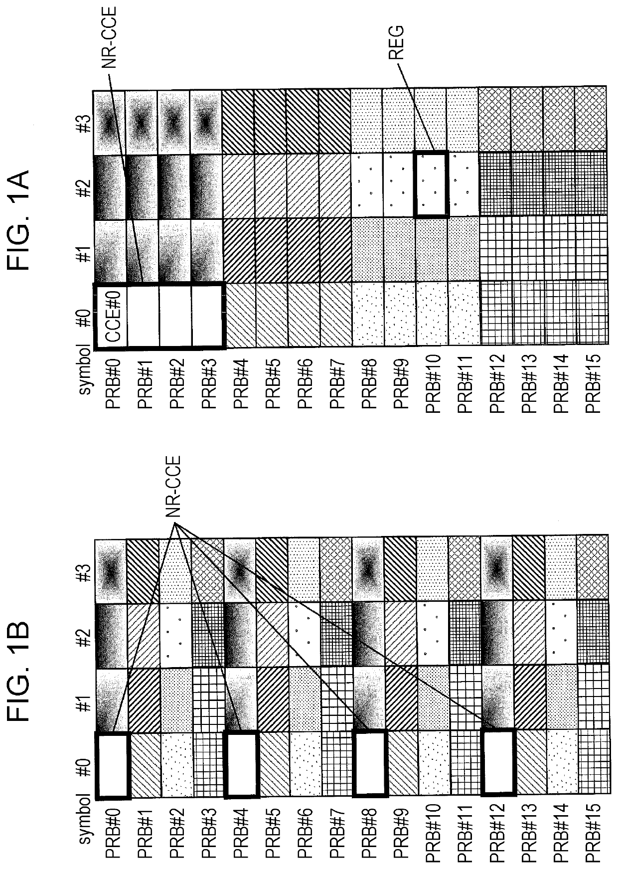
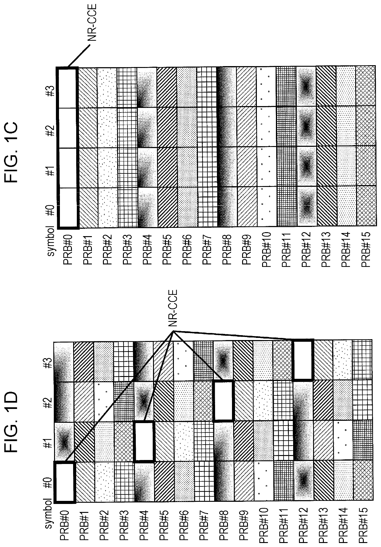
[0101]FIGS. 10A to 10C illustrate REG mapping examples when the number of REGs per CCE is 4 (=22), and the REG bundling size is 2 (=21).
[0102]In FIGS. 10A to 10C, the REG mapping is the time first mapping. That is, REGs tha...
operation example 1-2
[0116]Cases in which the number of symbols in a CORESET is a power of 2 have been described in operation example 1-1. In contrast, a case in which the number of symbols in a CORESET is a value other than a power of 2 will be described in operation example 1-2.
[0117]For example, when the number of symbols in a CORESET is a number of symbols other than a power of 2, REG mapping is set as a reference of REG mapping for the number of symbols which is larger than the number of symbols in a CORESET and which is a power of 2 closest thereto.
[0118]Specifically, when the number of symbols in a CORESET is 3, the last symbol is punctured or rate-matched in REG mapping (see, for example, FIG. 10C) in which the number of symbols is 4 (=22), which is described above in operation example 1-1, to thereby set REG mapping for the symbols in the CORESET, as illustrated in FIG. 13.
[0119]With such an arrangement, the number of REGs that are actually used differs from that in the reference REG mapping, b...
PUM
 Abstract
Description
Claims
Application Information